Learn how to roll out a successful edge AI solution across your organization in just 5 steps.
The demand for edge computing is higher than ever, driven by the pandemic, the need for more efficient business processes, as well as key advances in the Internet of Things (IoT), 5G, and AI. In a study published by IBM in May 2021, 94% of surveyed executives said that their organizations will implement edge computing in the next 5 years.
Edge AI, the combination of edge computing and AI, is a critical piece of the software-defined business. From smart hospitals and cities to cashierless shops to self-driving cars, all are powered by AI applications running at the edge.
Transforming business with intelligence driven by AI at the edge is just that, a transformation, which means it can be complicated. Whether you are starting your first AI project or looking at infrastructure blueprints and expansions, these five steps will help set your edge AI projects up for success.
Figure 1. Steps to get started with edge AI
1. Identify a use case
When it comes to getting started with edge AI, it is important to identify the right use case, whether it be to drive operational efficiency, financial impact, or social initiatives. For example, shrinkage in retail is a $100B problem that can be mitigated by machine learning and deep learning. Even a 10% reduction represents billions in revenue.
When selecting a use case for getting started with edge AI, consider the following factors.
Business impact: Successful AI projects must be of high enough value to the business to make them worth the time and resources needed to get them started.
Key stakeholders: Teams involved in AI projects include developers, IT, security operations (SecOps), partners, system integrators, application vendors, and more. Engage these teams early in the process for the best outcomes.
Success criteria: Define the end goal at the beginning to make sure that projects do not drift due to scope creep.
Timeframe: AI takes time and is an iterative process. Identifying use cases that have a long-term impact on the business will ensure that solutions remain valuable in the long term.
2. Evaluate your data and application requirements
With billions of sensors located at edge locations, it is generally a data-rich environment. This step requires understanding what data is going to be used for training an AI application as well as inference, which leads to action.
Getting labeled data can be daunting, but there are ways to solve this.
Leverage internal expertise: If you are trying to automate a process, use the experts who do the task manually to label data.
Synthetic data: Using annotated information that computer simulations or algorithms generate is a technique often used when there is limited training data or when the inference data will vary greatly from the original data sets.
Crowdsourced data: Leveraging your audience to help label large quantities of data has been effective for some companies. Examples include open-source data sets, social media content, or even self-checkout machines that collect information based on customer input.
If you have the quantity and quality of data required to train or retrain your AI models, then you can move on to the next step.
3. Understand edge infrastructure requirements
One of the most important and costly expenses when rolling out an edge AI solution is infrastructure. Unlike data centers, edge computing infrastructure must take into additional considerations around performance, bandwidth, latency, and security.
Start by looking at the existing infrastructure to understand what is already in place and what needs to be added. Here are some of the infrastructure items to consider for your edge AI platform.
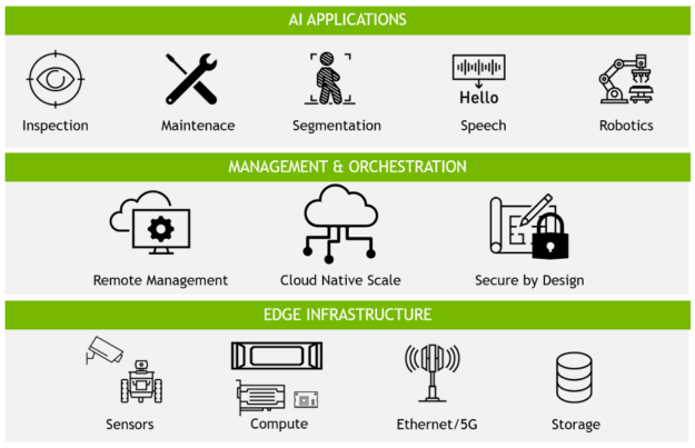
Figure 2. Edge AI infrastructure includes hardware, sensors, and AI software
Sensors: Most organizations today are relying on cameras as the main edge devices, but sensors can include chatbots, radar, lidar, temperature sensors, and more.
Compute systems: When sizing compute systems, consider the performance of the application and the limitations at the edge location, including space, power constraints, and heat. When these limiting factors are determined, you can then understand the performance requirements of your application.
Network: The main consideration for networking is how fast of a response you need for the use case to be viable, or how much data and whether real-time data must be transported across the network. Due to latency and reliability, wired networks are used where possible, though wireless is an option when needed.
Management: Edge computing presents unique challenges in the management of these environments. Organizations should consider solutions that solve the needs of edge AI, namely scalability, performance, remote management, resilience, and security.
Infrastructure is directly connected to the immediate use-case solution, but it is important to build with a mind to additional use cases that may be deployed at the same location.
4. Roll out your edge AI solution
When it comes to rolling out an edge AI application, testing AI applications at the edge is critical for ensuring success. An edge AI proof-of-concept (POC) is usually deployed at a handful of locations and can take anywhere from 3-12 months.
To ensure a smooth transition from POC to production, it is important to take into account what the end solution will look like. Here are some things to consider when rolling out an AI application.
Design for scale: POCs are generally limited to one or a handful of locations but if successful, they must scale to hundreds or even thousands of locations.
Constrain scope: AI applications improve over time. Different use cases will have different accuracy requirements that can be defined in the success criteria.
Prepare for change: Edge AI has many variables, which means even the best-laid plans will change. Ensure that the rollout is flexible without compromising the defined success criteria.
5. Celebrate your success
Edge AI is a transformational technology that helps businesses improve experience, speed, and operational efficiency. Many organizations have multiple edge use cases to roll out, which is why celebrating success is so important. Companies that highlight successes are more likely to drive interest, support, and funding for future edge AI projects.
Get started with end-to-end edge AI
As a leader in AI, NVIDIA has worked with customers and partners to create edge computing solutions that deliver powerful, distributed compute; secure remote management; and compatibility with industry-leading technologies.
Organizations can easily get started with NVIDIA LaunchPad, which provides immediate, short-term access to the necessary hardware and software stacks to experience end-to-end solution workflows in the areas of AI, data science, 3D design collaboration, and simulation, and more. Curated labs on LaunchPad help developers, designers, and IT professionals speed up the creation and deployment of modern, data-intensive applications.
Join us on May 26 to learn how you can leverage accelerated AI frameworks to build high performance zero-trust solutions with reduced friction and fewer lines of code.
I’ve originally posted this on self-hosted subreddit and it was really helpful to get me started.
My youngest son has Autism Spectrum Disorder (ASD), he’s 5 now. Recently he developed a habit of taking off his clothes and playing around without any clothes on! I already have a few cameras around the house, however, I was wondering if anyone knows a solution that can detect if my son is moving around the house without any clothes on so I can fire up automation and play a pre-recorded voice note on speakers in the house asking him to put on his clothes again!
So I’ve managed to get a live camera feed into Hom Assistant, using (https://github.com/snowzach/doods2) also was able to detect objects and persons using (tensorflow) and HA saves a snapshot for labels I want to capture, such as “person” or “people”. Seems to be working just fine.
I was looking for some pre-trained models to detect nudity / NSFW and found some such as: https://github.com/minto5050/NSFW-detection. However, I couldn’t manage to upload this model and run it for some reason. I’ve downloaded the model and labels files and placed them in the models and declared it in the config file but it isn’t working.
Can you guys help me? I don’t know how to solve this problem. I copied one of the kaggle works and changed the building part. For LeNet build this code worked but I tried that with VGG16 but it gives me error I couldn’t solve that.
Hello everyone, I have some problem with my task. I want to use LeNet for emotion detection but I tried everything and I stuck on that model fit part. I dont know much about AI. Can you guys help me and show the where is my mistake?
I am looking to get help running the TFLM code, which requires C++, with my nRF52 project which is written in C. Is this supported anywhere? How would you go about it? Is this the correct subreddit? Anything helps, many thanks!
Join NVIDIA and Google Cloud for a live webinar on May 25 to learn how to build a machine learning application to predict bike rental durations 5X faster.
Here’s how Pony.ai, which develops autonomous driving systems for robotaxis and trucks, uses GPU technology to develop a highly efficient data processing pipeline.
Just as humans rely on eyes to see, autonomous vehicles use sensors to gather information. These sensors collect a massive amount of data, which requires efficient onboard data processing for the vehicle to react quickly to situations on the road. This capability is crucial to autonomous vehicle safety and critical to making the virtual driver smarter.
With the need for redundant and diverse sensors and computing systems, it is challenging to design and optimize the processing pipeline. In this post, we present the evolution of Pony.ai’s on-vehicle sensor data processing pipeline.
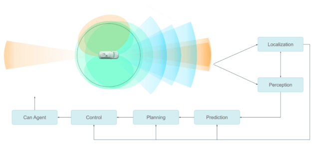
Pony.ai’s sensor setup includes multiple cameras, LiDARs, and radars. An upstream module synchronizes sensors, encapsulates the data into pieces of messages, and sends them to downstream modules that use them to segment, classify, and detect objects, and so on
Each type of sensor data might have multiple modules, and the user algorithm could be either traditional or neural-network-based.
Figure 1. Block diagram of Pony’s autonomous driving sensing system
This entire pipeline must run at the highest levels of efficiency. The safety of our passengers is our number one priority. The sensor data processing system affects safety in two aspects.
First, one of the deciding factors of safety is how fast the autonomous driving system deals with the sensor data. If the perception and localization algorithms get the sensor data with a delay of hundreds of milliseconds, then the decision made by the vehicle would be too late.
Second, the whole HW/SW system must be reliable for long-term success. Consumers will never want to buy or take a ride on an autonomous vehicle that starts having problems several months after being manufactured. This is critical in the mass-production stage.
Processing sensor data efficiently
Easing the bottlenecks in the sensor processing pipeline required a multi-faceted approach, taking into account the sensor, GPU architecture, and GPU memory.
From sensor to GPU
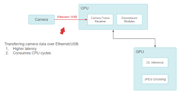
When Pony.ai was founded, our original sensor setup consisted of off-the-shelf components. We used USB- and ethernet-based models for the cameras, which were directly connected to the on-vehicle computer, and the CPU was responsible for reading data from the USB/Ethernet interface.
Figure 2. Block diagram showing the pipeline from the camera, to the CPU, to the GPU.
Transferring camera data over ethernet/USB provides higher latency but consumes CPU cycles.
While this functioned well, there was a fundamental issue with the design. The USB and the Ethernet-camera interfaces (GigE-camera) were CPU-consuming. With more and higher resolution cameras added, the CPUs quickly became overwhelmed and incapable of performing all the I/O operations. It was difficult for this design to be scalable while maintaining sufficiently low latency.
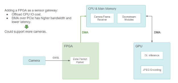
We solved the problem by adding an FPGA-based sensor gateway for cameras and LiDARs.
Figure 3. FPGA as a sensor gateway (sensors showing only the camera)
Adding an FPGA as a sensor gatewayoffloads the CPU I/O cost, but DMA over PCIe has higher bandwidth and lower latency, so it could support more cameras.
FPGA handles the camera trigger and synchronization logic to provide better sensor fusion. When one or more camera data packets are ready, a DMA transfer is triggered to copy the data from the FPGA to the main memory through the PCIe bus. The DMA engine does this on the FPGA, and the CPU is freed up. It not only opens the CPU’s I/O resources but also reduces data transfer latency, yielding a more scalable sensor setup.
Because the camera data is used by many neural network models running on GPUs, it still must be copied to GPU memory after it has been transferred from FPGA to CPU through DMA. So, a CUDA HostToDevice memory copy is required somewhere, which takes ~1.5 ms for a single frame of an FHD camera image.
However, we wanted to further reduce this latency. Ideally, the camera data should be directly transferred into the GPU memory without being routed through the CPU.
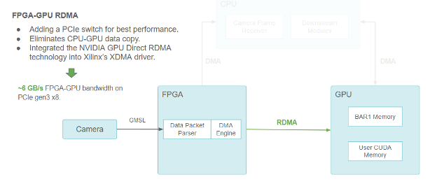
Figure 4. Same block diagram showing the camera/FPGA/CPU/GPU pipeline, but using RDMA to communicate between FPGA and GPU.
Using FPGA-GPU RDMA, we added a PCIe switch for best performance. This solution eliminated the CPU-GPU data copy. We also integrated NVIDIA GPU Direct RDMA technology into Xilinx’s XDMA driver, for ~6 GB/s FPGA-GPU bandwidth on PCIe Gen3 x8.
We achieved this goal by using the NVIDIA GPU Direct RDMA. GPU Direct RDMA enables us to preallocate a chunk of CUDA memory accessible to PCIe peers through the PCIe BARs (Base Address Register, which defines linear windows of PCIe address space).
It also provides a series of kernel-space APIs for the third-party device driver to obtain the GPU memory physical address. These APIs facilitate the DMA engines in third-party devices to send and read data directly to and from the GPU memory just like it sends and reads data to and from the main memory.
The GPU Direct RDMA reduces the latency by eliminating the CPU-to-GPU copy and achieves the highest bandwidth ~6 GB/s under PCIe Gen3 x8, which has a theoretical limit of 8 GB/s.
Scaling across GPUs
Due to the increasing compute workload, we needed more than one GPU. With more and more GPUs added to the system, communication between GPUs might also become a bottleneck. Going through the CPU through a staging buffer increases the CPU cost and limit the overall bandwidth.
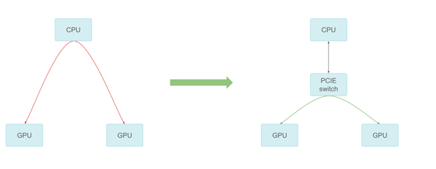
Figure 5. GPU-GPU communication by PCIe switch
We added a PCIe switch that provides the best possible peer-to-peer transfer performance. The peer-to-peer communication can reach PCIe line speed in our measurement, thus providing much better scaling across multiple GPUs.
Offloading computing to dedicated hardware
We also offloaded tasks that previously ran on CUDA cores to dedicated hardware to accelerate sensor data processing.
For example, when encoding an FHD camera image into a JPEG string, the NvJPEG library takes ~4ms on a single CPU thread with an RTX5000 GPU. The NvJPEG might consume CPU and GPU resources because some of its phases, like Huffman encoding, might be purely on the CPU.
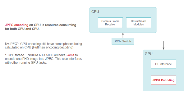
Figure 6. Block diagram showing data flow with JPEG encoding using the NvJPEG library on GPU.
JPEG encoding on GPU is resource-consuming for both GPU and CPU. NvJPEG GPU encoding still has some phases being calculated on CPU (Huffman encoding and decoding). One CPU thread plus the NVIDIA RTX 5000 takes ~4ms to encode one FHD image into JPEG. This also interferes with other running GPU tasks.
We adopted the NVIDIA Video Codec for on-vehicle use to relieve the CPU and GPU (CUDA part) from doing image encoding and decoding. This codec uses encoders in a dedicated portion of the GPU. It is part of the GPU, but it does not conflict with other CUDA resources used for running kernels and deep learning models.
We have also been migrating our image compression format from JPEG to HEVC (H.265), by using the dedicated hardware video encoder on NVIDIA GPUs. We achieved an improvement in the encoding speed and freed up both CPU and GPU resources for other tasks.
It takes ~3 ms to encode an FHD image fully on GPU without hurting its CUDA performance. The performance is measured in I-frame-only mode, which ensures consistent quality and compression artifacts across frames.
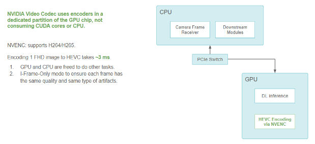
Figure 7. Block diagram showing data flow with HEVC encoding, which avoids consuming CUDA cores or the CPU.
NVIDIA Video Codec uses encoders in a dedicated partition of the GPU chip that does not consume CUDA cores or CPU. NVENC supports H264/H265. Encoding one FHD image to HEVC takes ~3 ms, so the GPU and CPU are freed to do other tasks. We used I-frame-only mode to ensure that each frame has the same quality and same type of artifacts.
On-GPU data flow
Another critical topic is the efficiency of sending the camera frames as messages to downstream modules.
We use Google’s protobuf to define a message. Take the CameraFrame message as an example. Camera specs and attributes are primitive types in the message. The real payload—camera data—must be defined as a bytes field in the main system memory, due to the limitation of protobuf.
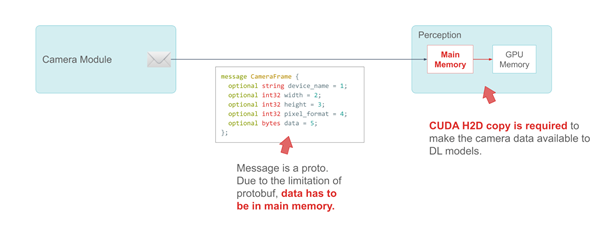
Figure 8. Example of a CameraFrame message
The message in the following code example is a proto. Due to the limitation of protobuf, data has to be in main memory.
CUDA H2D copy is required to make the camera data available to DL models.
We use a publisher-subscriber model with zero-copy message passing among modules to share information. Many subscriber modules of this CameraFrame message use the camera data to make deep learning inferences.
In the original design, when such a module received the message, it would have had to call a CUDA HostToDevice memory copy to transfer the camera data to the GPU before the inference.
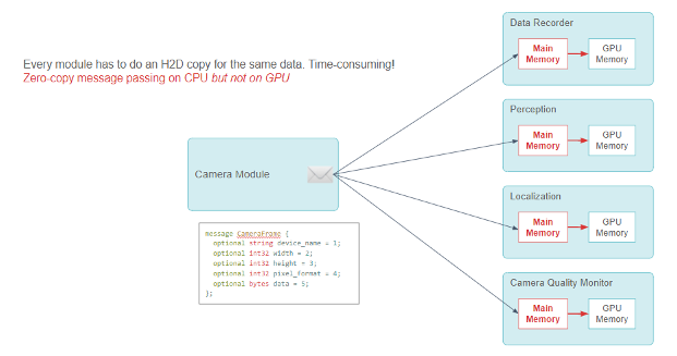
Figure 9. Block diagram showing a Publisher-Subscriber model that the camera module sends a CameraFrame message to multiple consumer modules. Each consumer module needs to do a CPU-to-GPU memory copy.
Every module has to do an H2D copy for the same data, which is time-consuming! The following code example shows the zero-copy message passing on the CPU but not on the GPU.
Every module must do the CUDA HostToDevice copy, which is redundant and resource-consuming. Although the zero-copy message passing framework works well on the CPU, it involves a lot of CPU-GPU data copy.
Figure 10. Zero-copy publisher-subscriber message passing with GPU support
We used the protobuf codegen plugin to enable the data fields in the GPU memory. The following code example shows the zero-copy message passing on the GPU. The GPUData field is in GPU memory.
We solved this issue by adding a new type of data, the GpuData field, into the protobuf code generator through protobuf’s plug-in API. GpuData supports the standard resize operation just like the CPU memory bytes field. However, its physical data storage is on-GPU.
When the subscriber modules receive the message, they can retrieve the GPU data pointer for direct use. Thus, we achieved full zero-copy throughout the entire pipeline.
Improving GPU memory allocation
When we call the resize function of the GpuData proto, it calls CUDA cudaMalloc. When the GpuData proto message is destroyed, it calls cudaFree.
These two API operations are not cheap because they must modify the GPU’s memory map. Each call could take ~0.1 ms.
Because this proto message is extensively used while the cameras are producing data non-stop, we should optimize the alloc/free cost of the GPU proto message.
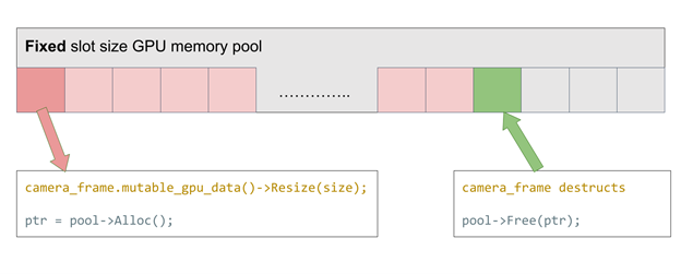
We implemented a fixed slot-size GPU memory to address this problem. The idea is simple: We maintain a stack of preallocated GPU memory slots that match our desired camera data frame buffer size. Every time alloc is called, we take one slot from the stack. Every time free is called, the slot is returned to the pool. The alloc/free time is near zero by re-using the GPU memory.
Figure 11. GPU memory pool supporting fixed allocation size only
What if we want to support cameras with different resolutions? Using this fixed-size memory pool, we must always allocate the largest possible size or initialize multiple memory pools with varying slot sizes. Either reduces efficiency.
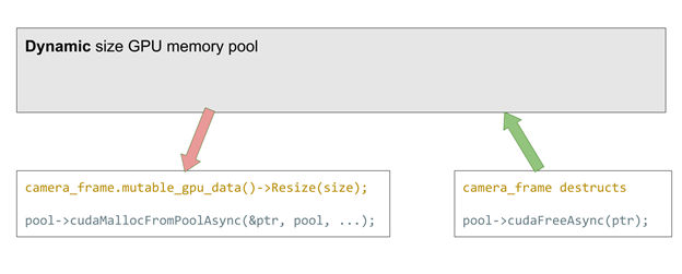
New features in CUDA 11.2 solved this issue. It officially supports cudaMemPool, which can be preallocated and later used for cudaMalloc and free. Compared with our previous implementation, it helps any allocation size. This greatly improves the flexibility at a tiny performance cost (~2us each allocation).
Figure 12. GPU memory pool supporting dynamic allocation size
camera_frame.mutable_gpu_data()->Resize(size);
pool->cudaMallocFromPoolAsync(&ptr, pool, ...);
camera_frame destructs
pool->cudaFreeAsync(ptr);
In both methods, the resize call falls back to conventional cudaMalloc and free when a memory pool overflows.
Cleaner data flow in YUV color space
We have achieved a highly efficient data flow with all the preceding optimizations of the hardware design and system software architecture. The next step is to optimize the data format itself.
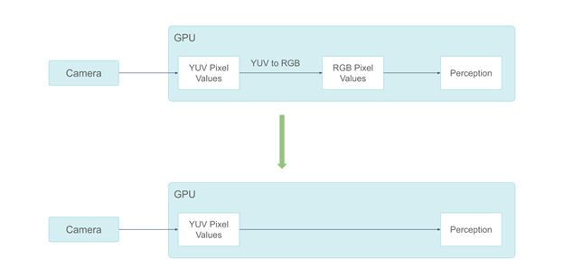
Our system used to process camera data in RGB color space. However, the ISP output of our cameras is in the YUV color space, and a conversion from YUV to RGB is performed on GPU, which takes ~0.3 ms. Also, some perception components do not need color information. Feeding RGB color pixels to them is wasteful.
Figure 13. Using the YUV format eliminates the colorspace conversion
For these reasons, we migrated from the RGB camera frames to the YUV frames. We chose to use the YUV420 pixel format because human vision is not as sensitive to chrominance information as to luminance information.
By adopting the YUV420 pixel format, we saved half of the GPU memory consumption. This also enabled us to send only the Y channel to the perception components, which do not require chrominance information, saving two-thirds of the GPU memory consumption compared to RGB.
Processing lidar data on-GPU
Besides camera data, we also process lidar data, which is more sparse, mostly on-GPU. While considering different types of Lidars, it is more difficult to process. We have taken several optimizations when processing lidar data:
Because lidar scan data contains a lot of physical information, we use the GPU-friendly Structure of Array instead of Array of Structures to describe the point cloud, making the GPU memory access pattern more coalesced instead of being scattered.
When some fields must be exchanged between CPU and GPU, we keep them in page-locked memory to accelerate the transfer.
The NVIDIA CUB library is extensively used in our processing pipeline, specifically the scan/select operations.
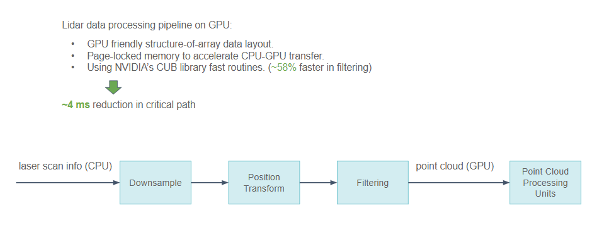
Figure 14. Block diagram showing pipeline from lidar sensor, to point cloud processing on GPU.
Lidar data processing pipeline on GPU produces the following results:
A GPU-friendly structure-of-array data layout.
Page-locked memory to accelerate the CPU-GPU transfer.
NVIDIA CUB library fast routines that are ~58% faster in filtering.
We have reduced the entire pipeline latency by ~4 ms in the critical path with all these optimizations.
Overall timeline
With all these optimizations, we can view our system tracing using our in-house timeline visualization tool.
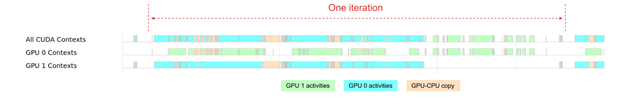
Figure 15. Overall timeline from sensor data to DL inference
The overall timeline shows the broad idea of how intensively we rely on our GPU today. Though the two GPUs are used for ~80% of the time, the workload of GPU0 and GPU1 are not ideally balanced. For GPU 0, it is heavily used throughout the perception module iteration. For GPU 1, it has more idle gaps in the middle of the iteration.
In the future, we will focus on further improving GPU efficiency.
Production-readiness
In the early days of development, the FPGA enabled us to easily experiment with our ideas in hardware-based sensor data processing. As our sensor-data processing unit becomes increasingly mature, we have been looking into the possibility of using a system-on-a-chip (SoC) to deliver a compact, reliable, and production-ready sensor data processor.
We found that the automotive-grade NVIDIA DRIVE Orin SoC perfectly meets our requirements. It is ASIL-rated, making it a great fit to run on production vehicles.
Migrating from FPGA to NVIDIA DRIVE Orin
In the early days of development, the FPGA enabled us to easily experiment with our ideas in hardware-based sensor data processing.
As our sensor-data processing unit becomes increasingly mature, we have been looking into the possibility of using a system-on-a-chip (SoC) to deliver a compact, reliable, and production-ready sensor data processor.
We found that the automotive-grade NVIDIA DRIVE Orin SoC perfectly meets our requirements. It is ASIL-rated, making it a great fit to run on production vehicles. Despite its compact size and low cost, it can connect to a wide spectrum of automotive-grade sensors and efficiently process large-scale sensor data.
We are going to use NVIDIA Orin to handle all the sensor signal processing, synchronization, packet collection, as well as camera frame encoding. We estimated that this design, combined with other architectural optimization, will save ~70% total BOM cost.
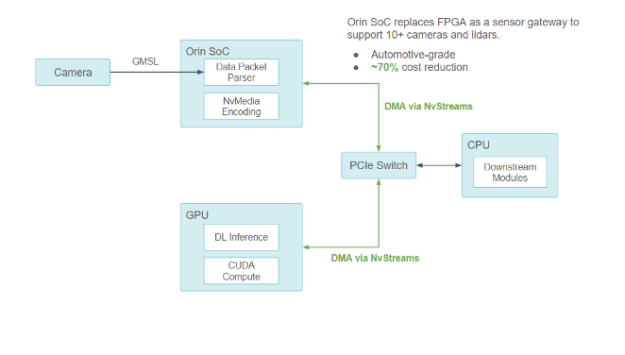
Figure 16. Using NVIDIA DRIVE Orin SoC as the new sensor gateway
Orin SoC replaces FPGA as a sensor gateway to support 10+ cameras and lidars, which are automotive-grade, for a ~70% cost reduction.
In collaboration with NVIDIA, we ensured that all communication among the Orin-CPU-GPU components goes through the PCIe bus with DMA support through NvStreams.
For compute-intensive DL work, the NVIDIA Orin SoC uses NvStream to transfer sensor data to the discrete GPU to process.
For non-GPU work, the NVIDIA Orin SoC uses NvStream to transfer data to the host CPU to process.
A level 2/3 compute platform application
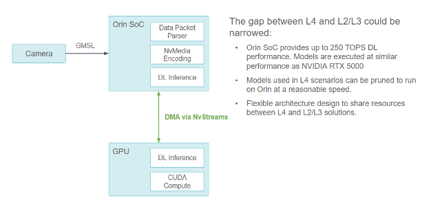
Figure 17. Block diagram showing a L2/L3 system camera pipeline achieved by removing the X86 CPU.
The gap between L4 and L2/L3 could be narrowed as Orin SoC provides up to 250 TOPS DL performance. Models are executed at a similar performance as NVIDIA RTX 5000, so models used in L4 scenarios can be pruned to run on Orin at a reasonable speed. The flexible architecture design can share resources between the L4 and L2/L3 solutions.
An excellent benefit of this design is that it has the potential to be used as an L2/L3 compute platform.
NVIDIA Orin provides 254 trillion operations per second of compute power that could potentially handle a similar workload as the RTX5000 discrete GPU being used on our current level 4 autonomous vehicle compute platform. However, it requires multiple optimizations to fully unleash the potential of the NVIDIA Orin SoC, such as:
Structural sparse network
DLA cores
Scaling across multiple NVIDIA Orin SoCs
Conclusion
The evolution of Pony’s sensor data processing pipeline has demonstrated our systematic approach toward high-efficiency data processing pipeline and enhanced system reliability, which helps achieve higher safety goals. The simple ideas behind this approach are:
Make the data flow simple and smooth. Data should be transferred directly to the location where it will get consumed, in the format that minimizes conversion overhead.
Use dedicated hardware for computation-intensive tasks and save the general-purpose computing resources for other tasks.
Resource sharing between level 4 and level 2 systems improves reliability and saves engineering costs.
This approach cannot be achieved by software or hardware alone, but by a joint effort of software and hardware co-design. We believe that this is crucial to satisfy the fast-growing computing needs with the production expectations.
Acknowledgments
This post includes years of evolution in Pony’s sensor data pipeline. The credit belongs to multiple teams and engineers who have continuously contributed to developing this highly efficient sensor data pipeline.

 Learn how to roll out a successful edge AI solution across your organization in just 5 steps.
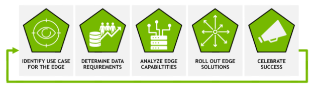
 Join us on May 26 to learn how you can leverage accelerated AI frameworks to build high performance zero-trust solutions with reduced friction and fewer lines of code.
 Join NVIDIA and Google Cloud for a live webinar on May 25 to learn how to build a machine learning application to predict bike rental durations 5X faster.
 Here’s how Pony.ai, which develops autonomous driving systems for robotaxis and trucks, uses GPU technology to develop a highly efficient data processing pipeline.