Hi, I just followed a python tensorflow object detection tutorial and was able to successfully get back an image with a label box. I was wondering how I could get the output in text. For example: The output image had successfully labeled 2 cars a toyota and 1 car as a honda. I want another output of a string that says “2 toyotas and 1 honda found”. I am not sure how to do this.
I’m trying to use OpenAI stable-baselines. This requires python 3.5 or higher. I set up my virtual environment etc., installed all dependencies. No problem. Then I try running a test script and it turns out that stable-baselines does not support Tensorflow 2. I need Tensorflow 1.15. No problem. I try to install tensorflow 1.15, but can’t because it is not available in pip anymore, for python3. Ok, so I need python 2.7 to use tensorflow 1.15… but then I can’t use stable-baselines, because it needs python 3… Help!
I was recently working on a project which required the use of the tensorflow.keras.optimizer module. I am getting no module name tensorflow.keras.optimizer error though tensorflow and keras are both installed and up to date and I am using tensorflow in the same file and it gave me no error. Also tensorflow.keras.preprocessing.image shows no module named that found. Thanks
Dear Community I have worked with pytorch before and now I started a project with Tensorflow.
In pytorch I can define a model and then send the parameters to the GPU with the command in the header. I googled how to achieve the same with Tensorflow (and Keras) but I have not found a satisfying answer.
Posted by Dhruv Shah, Intern, and Brian Ichter, Research Scientist, Robotics at Google
Advances in reinforcement learning (RL) for robotics have enabled robotic agents to perform increasingly complex tasks in challenging environments. Recent results show that robots can learn to fold clothes, dexterously manipulate a rubik’s cube, sort objects by color, navigate complex environments and walk on difficult, uneven terrain. But “short-horizon” tasks such as these, which require very little long-term planning and provide immediate failure feedback, are relatively easy to train compared to many tasks that may confront a robot in a real-world setting. Unfortunately, scaling such short-horizon skills to the abstract, long horizons of real-world tasks is difficult. For example, how would one train a robot capable of picking up objects to rearrange a room?
Hierarchical reinforcement learning (HRL), a popular way of solving this problem, has achieved some success in a variety of long-horizon RL tasks. HRL aims to solve such problems by reasoning over a bank of low-level skills, thus providing an abstraction for actions. However, the high-level planning problem can be further simplified by abstracting both states and actions. For example, consider a tabletop rearrangement task, where a robot is tasked with interacting with objects on a desk. Using recent advances in RL, imitation learning, and unsupervised skill discovery, it is possible to obtain a set of primitive manipulation skills such as opening or closing drawers, picking or placing objects, etc. However, even for the simple task of putting a block into the drawer, chaining these skills together is not straightforward. This may be attributed to a combination of (i) challenges with planning and reasoning over long horizons, and (ii) dealing with high dimensional observations while parsing the semantics and affordances of the scene, i.e., where and when the skill can be used.
In “Value Function Spaces: Skill-Centric State Abstractions for Long-Horizon Reasoning”, presented at ICLR 2022, we address the task of learning suitable state and action abstractions for long-range problems. We posit that a minimal, but complete, representation for a higher-level policy in HRL must depend on the capabilities of the skills available to it. We present a simple mechanism to obtain such a representation using skill value functions and show that such an approach improves long-horizon performance in both model-based and model-free RL and enables better zero-shot generalization.
Our method, VFS, can compose low-level primitives (left) to learn complex long-horizon behaviors (right).
Building a Value Function Space The key insight motivating this work is that the abstract representation of actions and states is readily available from trained policies via their value functions. The notion of “value” in RL is intrinsically linked to affordances, in that the value of a state for skill reflects the probability of receiving a reward for successfully executing the skill. For any skill, its value function captures two key properties: 1) the preconditions and affordances of the scene, i.e., where and when the skill can be used, and 2) the outcome, which indicates whether the skill executed successfully when it was used.
Given a decision process with a finite set of k skills trained with sparse outcome rewards and their corresponding value functions, we construct an embedding space by stacking these skill value functions. This gives us an abstract representation that maps a state to a k-dimensional representation that we call the Value Function Space, or VFS for short. This representation captures functional information about the exhaustive set of interactions that the agent can have with the environment, and is thus a suitable state abstraction for downstream tasks.
Consider a toy example of the tabletop rearrangement setup discussed earlier, with the task of placing the blue object in the drawer. There are eight elementary actions in this environment. The bar plot on the right shows the values of each skill at any given time, and the graph at the bottom shows the evolution of these values over the course of the task.
Value functions corresponding to each skill (top-right; aggregated in bottom) capture functional information about the scene (top-left) and aid decision-making.
At the beginning, the values corresponding to the “Place on Counter” skill are high since the objects are already on the counter; likewise, the values corresponding to “Close Drawer” are high. Through the trajectory, when the robot picks up the blue cube, the corresponding skill value peaks. Similarly, the values corresponding to placing the objects in the drawer increase when the drawer is open and peak when the blue cube is placed inside it. All the functional information required to affect each transition and predict its outcome (success or failure) is captured by the VFS representation, and in principle, allows a high-level agent to reason over all the skills and chain them together — resulting in an effective representation of the observations.
Additionally, since VFS learns a skill-centric representation of the scene, it is robust to exogenous factors of variation, such as background distractors and appearances of task-irrelevant components of the scene. All configurations shown below are functionally equivalent — an open drawer with the blue cube in it, a red cube on the countertop, and an empty gripper — and can be interacted with identically, despite apparent differences.
The learned VFS representation can ignore task-irrelevant factors such as arm pose, distractor objects (green cube) and background appearance (brown desk).
Robotic Manipulation with VFS This approach enables VFS to plan out complex robotic manipulation tasks. Take, for example, a simple model-based reinforcement learning (MBRL) algorithm that uses a simple one-step predictive model of the transition dynamics in value function space and randomly samples candidate skill sequences to select and execute the best one in a manner similar to the model-predictive control. Given a set of primitive pushing skills of the form “move Object A near Object B” and a high-level rearrangement task, we find that VFS can use MBRL to reliably find skill sequences that solve the high-level task.
A rollout of VFS performing a tabletop rearrangement task using a robotic arm. VFS can reason over a sequence of low-level primitives to achieve the desired goal configuration.
To better understand the attributes of the environment captured by VFS, we sample the VFS-encoded observations from a large number of independent trajectories in the robotic manipulation task and project them onto a two-dimensional axis using the t-SNE technique, which is useful for visualizing clusters in high-dimensional data. These t-SNE embeddings reveal interesting patterns identified and modeled by VFS. Looking at some of these clusters closely, we find that VFS can successfully capture information about the contents (objects) in the scene and affordances (e.g., a sponge can be manipulated when held by the robot’s gripper), while ignoring distractors like the relative positions of the objects on the table and the pose of the robotic arm. While these factors are certainly important to solve the task, the low-level primitives available to the robot abstract them away and hence, make them functionally irrelevant to the high-level controller.
Visualizing the 2D t-SNE projections of VFS embeddings show emergent clustering of equivalent configurations of the environment while ignoring task-irrelevant factors like arm pose.
Conclusions and Connections to Future Work Value function spaces are representations built on value functions of underlying skills, enabling long-horizon reasoning and planning over skills. VFS is a compact representation that captures the affordances of the scene and task-relevant information while robustly ignoring distractors. Empirical experiments reveal that such a representation improves planning for model-based and model-free methods and enables zero-shot generalization. Going forward, this representation has the promise to continue improving along with the field of multitask reinforcement learning. The interpretability of VFS further enables integration into fields such as safe planning and grounding language models.
Acknowledgements We thank our co-authors Sergey Levine, Ted Xiao, Alex Toshev, Peng Xu and Yao Lu for their contributions to the paper and feedback on this blog post. We also thank Tom Small for creating the informative visualizations used in this blog post.
Join this webinar from Metropolis on May 18 or 19 to learn how synthetic data can transform your AI development efforts, including using the NVIDIA Omniverse Replicator.
Inline processing of network packets using GPUs is a packet analysis technique useful to a number of different applications.
The inline processing of network packets using GPUs is a packet-analysis technique useful to a number of different application domains: signal processing, network security, information gathering, input reconstruction, and so on.
The main requirement of these application types is to move received packets into GPU memory as soon as possible, to trigger the CUDA kernel responsible to execute parallel processing on them.
The general idea is to create a continuous asynchronous pipeline able to receive packets from the network card directly into the GPU memory. You also dedicate a CUDA kernel to process the incoming packets without needing to synchronize the GPU and CPU.
An effective application workflow involves creating a continuous asynchronous pipeline coordinated between the following player components using lockless communication mechanisms:
A network controller to feed the GPU memory with received network packets
A CPU to query the network controller to get info about received packets
A GPU to receive the packets info and process them directly into GPU memory
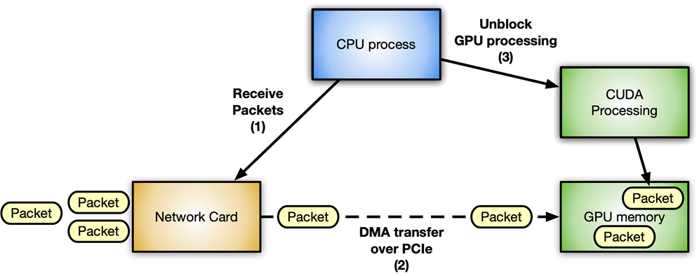
Figure 1 shows a typical packet workflow scenario for an accelerated inline packet processing application using an NVIDIA GPU and a ConnectX network card.
Avoiding latency is crucial in this context. The more the communications between different components are optimized, the more the system is responsive with increased throughput. Every step has to happen inline as soon as the resource that it needs is available, without blocking any of the other waiting components.
You can clearly identify two different flows:
Data flow: Optimized data (network packets) exchange between network card and GPU over the PCIe bus.
Control flow: The CPU orchestrates the GPU and network card.
Data flow
The key is optimized data movement (send or receive packets) between the network controller and the GPU. It can be implemented through the GPUDirect RDMA technology, which enables a direct data path between an NVIDIA GPU and third-party peer devices such as network cards, using standard features of the PCI Express bus interface.
GPUDirect RDMA relies on the ability of NVIDIA GPUs to expose portions of device memory on a PCI Express base address register (BAR) region. For more information, see Developing a Linux Kernel Module using GPUDirect RDMA in the CUDA Toolkit documentation. The Benchmarking GPUDirect RDMA on Modern Server Platforms post provides more in-depth analysis of GPUDirect RDMA bandwidth and latency in case of network operations (send and receive) performed with standard IB verbs using different system topologies.
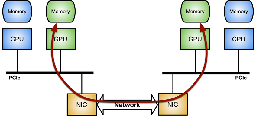
Figure 2. NVIDIA GPUDirect RDMA enables a direct path for data exchange between the GPU and third-party peer devices using standard features of PCI Express
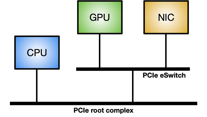
To enable GPUDirect RDMA on a Linux system, the nvidia-peermem module is required (available in CUDA 11.4 and later). Figure 3 shows the ideal system topology to maximize the GPUDirect RDMA internal throughput: a dedicated PCIe switch between GPU and NIC, rather than going through the system PCIe connection shared with other components.
Figure 3. Ideal topology to maximize internal data throughput between the network controller and GPU
Control flow
The CPU is the main player coordinating and synchronizing activities between the network controller and the GPU to wake up the NIC to receive packets into GPU memory and notify the CUDA workload that new packets are available for processing.
When dealing with a GPU, it’s really important to emphasize the asynchrony between CPU and GPU. For example, consider a simple application executing the following three steps in the main loop:
Receive packets.
Process packets.
Send back modified packets.
In this post, I cover four different methods to implement the control flow in this kind of application, including pros and cons.
Method 1
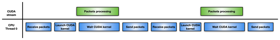
Figure 4 shows the easiest but least effective approach: a single CPU thread is responsible for receiving packets, launches the CUDA kernel to process them, waits for the completion of the CUDA kernel, and sends the modified packets back to the network controller.
Figure 4. Workflow of a single CPU passing a packet to the CUDA kernel and waiting for completion to take the next step
If packet processing is not so intensive, this approach may perform worse than just processing packets with the CPU, without the GPU involved. For example, you might have a high degree of parallelism to solve a difficult and time-consuming algorithm on packets.
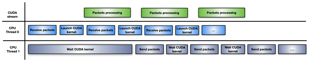
Method 2
In this approach, the application splits the CPU workload into two CPU threads: one for receiving packets and launching GPU processing, and the other for waiting for completion of GPU processing and transmitting modified packets over the network (Figure 5).
Figure 5. Split CPU threads to process packets through a GPU
A drawback of this approach is the launch of a new CUDA kernel for each burst of accumulated packets. The CPU has to pay for CUDA kernel launch latency for every iteration. If the GPU is overwhelmed, the packet processing may not be executed immediately, causing a delay.
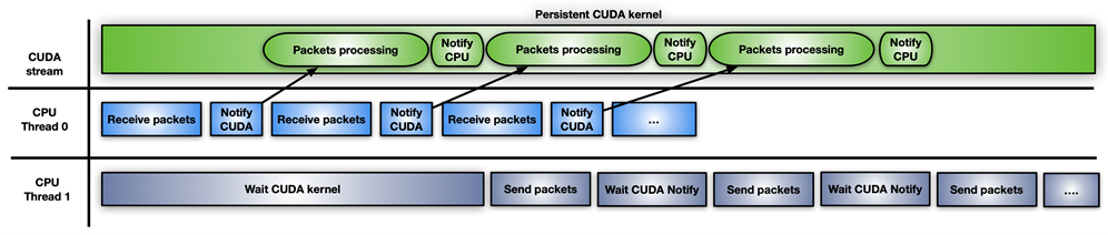
Method 3
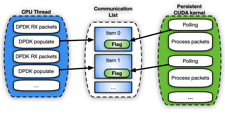
Figure 6 shows the third approach, which involves the use of a CUDA persistent kernel.
Figure 6. Inline packet processing using a persistent CUDA kernel.
A CUDA persistent kernel is a pre-launched kernel that is busy waiting for a notification from the CPU: New packets have arrived and are ready to be processed. When the packets are ready, the kernel notifies the second CPU thread that it can move forward to send them.
The easiest way to implement this notification system is to share some memory between CPU and GPU using a busy wait-on-flag update mechanism. While GPUDirect RDMA is meant for direct access to GPU memory from third-party devices, you can use these same APIs to create perfectly valid CPU mappings of the GPU memory. The advantage of a CPU-driven copy is the small overhead involved. This feature can be enabled today through the GDRCopy library.
Directly mapping GPU memory for signaling makes the memory modifiable from the CPU and less latency expensive for the GPU during polling. You can also put that flag in CPU pinned memory visible from the GPU, but the CUDA kernel polling on CPU memory flag would consume more PCIe bandwidth and increase the overall latency.
The problem with this fast solution is that it is risky and not supported by the CUDA programming model. GPU kernels cannot be preempted. If not written correctly, the persistent kernel may loop forever. Also, a long-running persistent kernel may lose synchronization with respect to other CUDA kernels, CPU activity, memory allocation status, and so on.
It also holds GPU resources (for example, streaming multiprocessors) that may not be the best option, in case the GPU is really busy with other tasks. If you use CUDA persistent kernels, you really must have a good handle on your application.
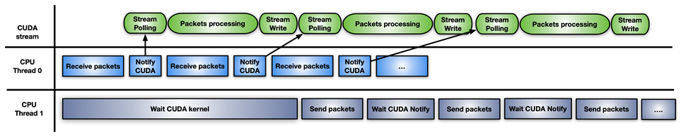
Method 4
The final approach is a hybrid solution of the previous ones: use CUDA stream memory operations to wait or update the notification flag, with pre-launching on the CUDA stream one CUDA kernel per set of received packets.
Figure 7. Hybrid approach to inline packet processing using a combination of models
The difference with this approach is that GPU HW is polling (with cuStreamWaitValue) on the memory flag rather than blocking the GPU streaming multiprocessors, and the packets’ processing kernel is triggered only when the packets are ready.
Similarly, when the processing kernel ends, cuStreamWriteValue notifies the CPU thread responsible for sending that the packets have been processed.
The downside of this approach is that the application must, from time to time, re-fill the GPU with a new sequence of cuStreamWaitValue + CUDA kernel + cuStreamWriteValue so as to not waste execution time with an empty stream not ready to process more packets. A CUDA Graph here can be a good approach for reposting on the stream.
Different approaches are suited to different application patterns.
DPDK and GPUdev
The Data Plane Development Kit (DPDK) is a set of libraries to help accelerate packet processing workloads running on a wide variety of CPU architectures and different devices.
In DPDK 21.11, NVIDIA introduced a new library named GPUdev to introduce the notion of GPU in the context of DPDK, and to enhance the dialog between CPU, network cards, and GPUs. GPUdev was extended with more features in DPDK 22.03.
The goals of the library are as follows:
Introduce the concept of a GPU device managed from a DPDK generic library.
Reduce the gap between the network card, GPU device, and CPU enhancing the communication.
Simplify the DPDK integration into GPU applications.
Expose GPU driver-specific features through a generic layer.
For NVIDIA-specific GPUs, the GPUdev library functionalities are implemented at DPDK driver level through the CUDA driver DPDK library. To enable all the gpudev available features for an NVIDIA GPU, DPDK must be built on a system having CUDA libraries and GDRCopy.
With features offered by this new library, you can easily implement inline packet processing with GPUs taking care of both data flow and control flows.
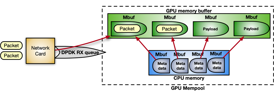
DPDK receives packets in a mempool, a continuous chunk of memory. With the following sequence of instructions, you can enable GPUDirect RDMA to allocate the mempool in GPU memory, registering it into the device network.
struct rte_pktmbuf_extmem gpu_mem;

gpu_mem.buf_ptr = rte_gpu_mem_alloc(gpu_id, gpu_mem.buf_len, alignment));

/* Make the GPU memory visible to DPDK */

rte_extmem_register(gpu_mem.buf_ptr, gpu_mem.buf_len,

                            NULL, gpu_mem.buf_iova, NV_GPU_PAGE_SIZE);

/* Create DMA mappings on the NIC */

rte_dev_dma_map(rte_eth_devices[PORT_ID].device, gpu_mem.buf_ptr,

                                   gpu_mem.buf_iova, gpu_mem.buf_len));

/* Create the actual mempool */

struct rte_mempool *mpool = rte_pktmbuf_pool_create_extbuf(... , &gpu_mem, ...);
Figure 8 shows the structure of the mempool:
Figure 8. Structure of the mempool for inline packet processing
For the control flow, to enable the notification mechanism between CPU and GPU, you can use the gpudev communication list: a shared memory structure between the CPU memory and the CUDA kernel. Each item of the list can hold the addresses of received packets (mbufs) and a flag to update about the status of processing that item (ready with packets, done with processing, and so on).
struct rte_gpu_comm_list {
    /** DPDK GPU ID that will use the communication list. */
    uint16_t dev_id;
    /** List of mbufs populated by the CPU with a set of mbufs. */
    struct rte_mbuf **mbufs;
    /** List of packets populated by the CPU with a set of mbufs info. */
    struct rte_gpu_comm_pkt *pkt_list;
    /** Number of packets in the list. */
    uint32_t num_pkts;
    /** Status of the packets’ list. CPU pointer. */
    enum rte_gpu_comm_list_status *status_h;
    /** Status of the packets’ list. GPU pointer. */
    enum rte_gpu_comm_list_status *status_d;
};
Example pseudo-code:
struct rte_mbuf * rx_mbufs[MAX_MBUFS];

int item_index = 0;

struct rte_gpu_comm_list *comm_list = rte_gpu_comm_create_list(gpu_id, NUM_ITEMS);

 while(exit_condition) {

...

// Receive and accumulate enough packets

    nb_rx += rte_eth_rx_burst(port_id, queue_id, &(rx_mbufs[0]), rx_pkts);

// Populate next item in the communication list.

    rte_gpu_comm_populate_list_pkts(&(p_v->comm_list[index]), rx_mbufs, nb_rx);

 ...

    index++;

}
For simplicity, assuming that the application follows the CUDA persistent kernel scenario, the polling side on the CUDA kernel would look something like the following code example:
__global__ void cuda_persistent_kernel(struct rte_gpu_comm_list *comm_list, int comm_list_entries)

{

    int item_index = 0;

    uint32_t wait_status;

     /* GPU kernel keeps checking exit condition as it can’t be preempted. */

    while (!exit_condition()) {

        wait_status = RTE_GPU_VOLATILE(comm_list[item_index].status_d[0]);

        if (wait_status != RTE_GPU_COMM_LIST_READY)

            continue;

         if (threadIdx.x num_pkts) {

            /* Each CUDA thread processes a different packet. */

            packet_processing(comm_list[item_index]->addr, comm_list[item_index]->size, ..);

        }

        __syncthreads();

         /* Notify packets in the items have been processed */

        if (threadIdx.x == 0) {

            RTE_GPU_VOLATILE(comm_list[item_index].status_d[0]) = RTE_GPU_COMM_LIST_DONE;

            __threadfence_system();

        }

         /* Wait for new packets on the next communication list entry. */

        item_index = (item_index+1) % comm_list_entries;

    }

}
Figure 9. Example workflow of the pseudo-code for the polling side in a persistent kernel
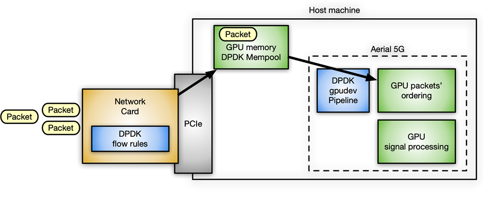
A concrete use case at NVIDIA that uses the DPDK gpudev library for inline packet processing is in the Aerial application framework for building high-performance, software-defined, 5G applications. In this case, packets must be received in GPU memory and reordered according to 5G-specific packet headers, with the effect that signal processing can start on the reordered payload.
Figure 10. Inline packet processing use case with DPDK gpudev in Aerial 5G software
l2fwd-nv application
To provide a practical example of how to implement inline packet processing and use the DPDK gpudev library, the l2fwd-nv sample code has been released on the /NVIDIA/l2fwd-nv GitHub repo. This is an extension of the vanilla DPDK l2fwd example enhanced with GPU capabilities. The application layout is to receive packets, swap MAC addresses (source and destination) for each packet, and transmit the modified packets.
L2fwd-nv provides an implementation example for all the approaches discussed in this post for comparison:
CPU only
CUDA kernels per set of packets
CUDA persistent kernel
CUDA Graphs
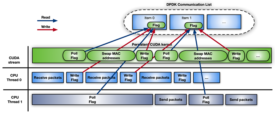
As an example, Figure 11 shows the timeline for CUDA persistent kernel with DPDK gpudev objects.
Figure 11. Example timeline for the CUDA persistent kernel using DPDK gpudev objects
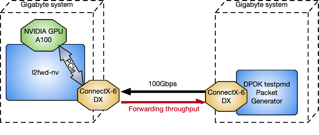
To measure l2fwd-nv performance against the DPDK testpmd packet generator, two Gigabyte servers connected back-to-back, have been used in Figure 12 with CPU: Intel Xeon Gold 6240R, PCIe gen3 dedicated switch, Ubuntu 20.04, MOFED 5.4, and CUDA 11.4.
Figure 12. Two Gigabyte server configurations to test l2fwd-nv performance
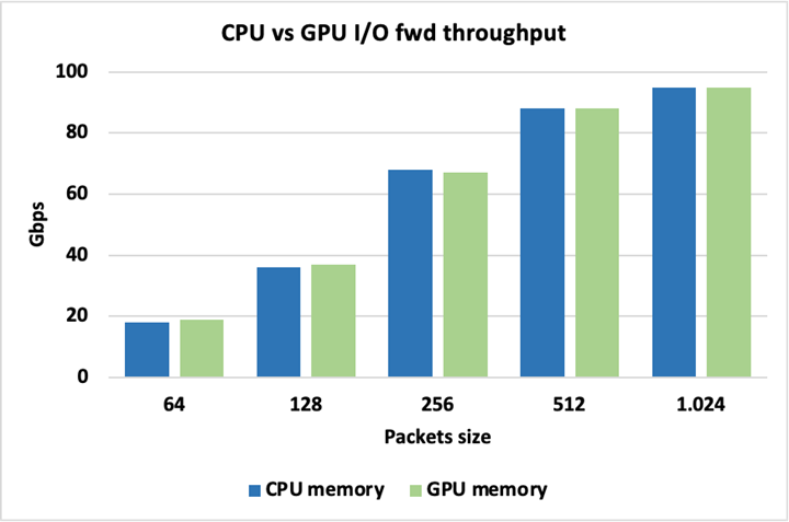
Figure 13 shows that peak I/O throughput is identical when using either CPU or GPU memory for the packets, so there is no inherent penalty for using one over the other. Packets here are forwarded without being modified.
Figure 13. Peak I/O throughput is identical
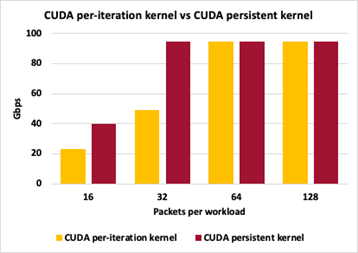
To highlight differences between different GPU packet handling approaches, Figure 14 shows the throughput comparison between Method 2 (CUDA kernel per set of packets) and Method 3 (CUDA persistent kernel). Both methods keep packet sizes to 1024 bytes, varying the number of accumulated packets before triggering the GPU work to swap packets’ MAC addresses.
Figure 14. Differences between GPU packet handling methods
For both approaches, 16 packets per iteration causes too many interactions in the control plane and peak throughput is not achieved. With 32 packets per iteration, the persistent kernel can keep up with peak throughput while individual launches per iteration still have too much control plane overhead. For 64 and 128 packets per iteration, both approaches are able to reach peak I/O throughput. Throughput measurements here are not at zero-loss packets.
Conclusion
In this post, I discussed several approaches to optimize inline packet processing using GPUs. Depending on your application needs, you can apply several workflow models to gain improved performance as a result of reduced latency. The DPDK gpudev library also helps simplify your coding efforts to achieve optimum results in the shortest amount of time.
Other factors to consider, depending on the application, include how much time to spend accumulating enough packets on the receive side before triggering the packet processing, how many threads are available to enhance, as much as possible, parallelism among different tasks, and how long the kernel should be persistent in the execution.


 Join this webinar from Metropolis on May 18 or 19 to learn how synthetic data can transform your AI development efforts, including using the NVIDIA Omniverse Replicator.

 Inline processing of network packets using GPUs is a packet analysis technique useful to a number of different applications.