Hello everyone, I have some problem with my task. I want to use LeNet for emotion detection but I tried everything and I stuck on that model fit part. I dont know much about AI. Can you guys help me and show the where is my mistake?
I am looking to get help running the TFLM code, which requires C++, with my nRF52 project which is written in C. Is this supported anywhere? How would you go about it? Is this the correct subreddit? Anything helps, many thanks!
Join NVIDIA and Google Cloud for a live webinar on May 25 to learn how to build a machine learning application to predict bike rental durations 5X faster.
Here’s how Pony.ai, which develops autonomous driving systems for robotaxis and trucks, uses GPU technology to develop a highly efficient data processing pipeline.
Just as humans rely on eyes to see, autonomous vehicles use sensors to gather information. These sensors collect a massive amount of data, which requires efficient onboard data processing for the vehicle to react quickly to situations on the road. This capability is crucial to autonomous vehicle safety and critical to making the virtual driver smarter.
With the need for redundant and diverse sensors and computing systems, it is challenging to design and optimize the processing pipeline. In this post, we present the evolution of Pony.ai’s on-vehicle sensor data processing pipeline.
Pony.ai’s sensor setup includes multiple cameras, LiDARs, and radars. An upstream module synchronizes sensors, encapsulates the data into pieces of messages, and sends them to downstream modules that use them to segment, classify, and detect objects, and so on
Each type of sensor data might have multiple modules, and the user algorithm could be either traditional or neural-network-based.
Figure 1. Block diagram of Pony’s autonomous driving sensing system
This entire pipeline must run at the highest levels of efficiency. The safety of our passengers is our number one priority. The sensor data processing system affects safety in two aspects.
First, one of the deciding factors of safety is how fast the autonomous driving system deals with the sensor data. If the perception and localization algorithms get the sensor data with a delay of hundreds of milliseconds, then the decision made by the vehicle would be too late.
Second, the whole HW/SW system must be reliable for long-term success. Consumers will never want to buy or take a ride on an autonomous vehicle that starts having problems several months after being manufactured. This is critical in the mass-production stage.
Processing sensor data efficiently
Easing the bottlenecks in the sensor processing pipeline required a multi-faceted approach, taking into account the sensor, GPU architecture, and GPU memory.
From sensor to GPU
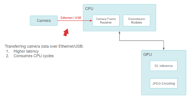
When Pony.ai was founded, our original sensor setup consisted of off-the-shelf components. We used USB- and ethernet-based models for the cameras, which were directly connected to the on-vehicle computer, and the CPU was responsible for reading data from the USB/Ethernet interface.
Figure 2. Block diagram showing the pipeline from the camera, to the CPU, to the GPU.
Transferring camera data over ethernet/USB provides higher latency but consumes CPU cycles.
While this functioned well, there was a fundamental issue with the design. The USB and the Ethernet-camera interfaces (GigE-camera) were CPU-consuming. With more and higher resolution cameras added, the CPUs quickly became overwhelmed and incapable of performing all the I/O operations. It was difficult for this design to be scalable while maintaining sufficiently low latency.
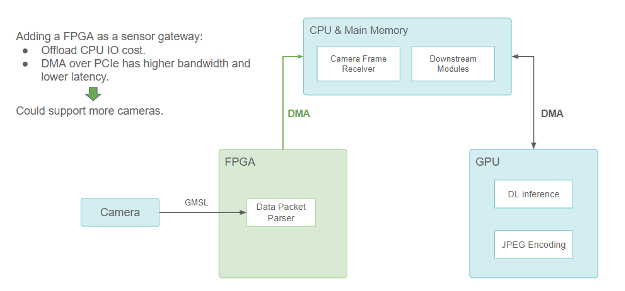
We solved the problem by adding an FPGA-based sensor gateway for cameras and LiDARs.
Figure 3. FPGA as a sensor gateway (sensors showing only the camera)
Adding an FPGA as a sensor gatewayoffloads the CPU I/O cost, but DMA over PCIe has higher bandwidth and lower latency, so it could support more cameras.
FPGA handles the camera trigger and synchronization logic to provide better sensor fusion. When one or more camera data packets are ready, a DMA transfer is triggered to copy the data from the FPGA to the main memory through the PCIe bus. The DMA engine does this on the FPGA, and the CPU is freed up. It not only opens the CPU’s I/O resources but also reduces data transfer latency, yielding a more scalable sensor setup.
Because the camera data is used by many neural network models running on GPUs, it still must be copied to GPU memory after it has been transferred from FPGA to CPU through DMA. So, a CUDA HostToDevice memory copy is required somewhere, which takes ~1.5 ms for a single frame of an FHD camera image.
However, we wanted to further reduce this latency. Ideally, the camera data should be directly transferred into the GPU memory without being routed through the CPU.
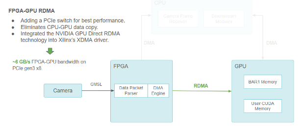
Figure 4. Same block diagram showing the camera/FPGA/CPU/GPU pipeline, but using RDMA to communicate between FPGA and GPU.
Using FPGA-GPU RDMA, we added a PCIe switch for best performance. This solution eliminated the CPU-GPU data copy. We also integrated NVIDIA GPU Direct RDMA technology into Xilinx’s XDMA driver, for ~6 GB/s FPGA-GPU bandwidth on PCIe Gen3 x8.
We achieved this goal by using the NVIDIA GPU Direct RDMA. GPU Direct RDMA enables us to preallocate a chunk of CUDA memory accessible to PCIe peers through the PCIe BARs (Base Address Register, which defines linear windows of PCIe address space).
It also provides a series of kernel-space APIs for the third-party device driver to obtain the GPU memory physical address. These APIs facilitate the DMA engines in third-party devices to send and read data directly to and from the GPU memory just like it sends and reads data to and from the main memory.
The GPU Direct RDMA reduces the latency by eliminating the CPU-to-GPU copy and achieves the highest bandwidth ~6 GB/s under PCIe Gen3 x8, which has a theoretical limit of 8 GB/s.
Scaling across GPUs
Due to the increasing compute workload, we needed more than one GPU. With more and more GPUs added to the system, communication between GPUs might also become a bottleneck. Going through the CPU through a staging buffer increases the CPU cost and limit the overall bandwidth.
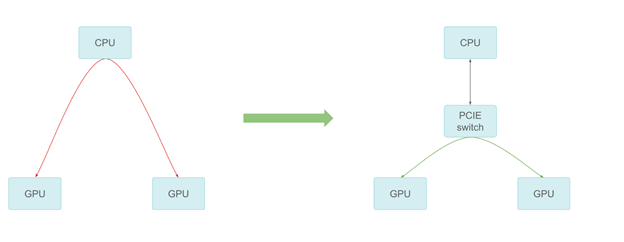
Figure 5. GPU-GPU communication by PCIe switch
We added a PCIe switch that provides the best possible peer-to-peer transfer performance. The peer-to-peer communication can reach PCIe line speed in our measurement, thus providing much better scaling across multiple GPUs.
Offloading computing to dedicated hardware
We also offloaded tasks that previously ran on CUDA cores to dedicated hardware to accelerate sensor data processing.
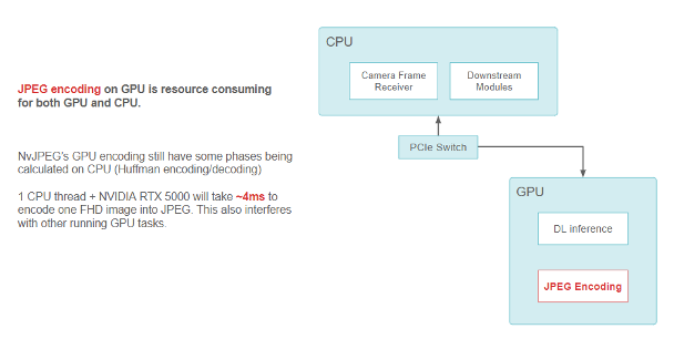
For example, when encoding an FHD camera image into a JPEG string, the NvJPEG library takes ~4ms on a single CPU thread with an RTX5000 GPU. The NvJPEG might consume CPU and GPU resources because some of its phases, like Huffman encoding, might be purely on the CPU.
Figure 6. Block diagram showing data flow with JPEG encoding using the NvJPEG library on GPU.
JPEG encoding on GPU is resource-consuming for both GPU and CPU. NvJPEG GPU encoding still has some phases being calculated on CPU (Huffman encoding and decoding). One CPU thread plus the NVIDIA RTX 5000 takes ~4ms to encode one FHD image into JPEG. This also interferes with other running GPU tasks.
We adopted the NVIDIA Video Codec for on-vehicle use to relieve the CPU and GPU (CUDA part) from doing image encoding and decoding. This codec uses encoders in a dedicated portion of the GPU. It is part of the GPU, but it does not conflict with other CUDA resources used for running kernels and deep learning models.
We have also been migrating our image compression format from JPEG to HEVC (H.265), by using the dedicated hardware video encoder on NVIDIA GPUs. We achieved an improvement in the encoding speed and freed up both CPU and GPU resources for other tasks.
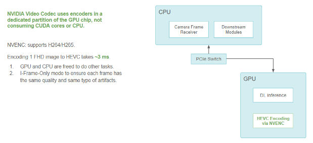
It takes ~3 ms to encode an FHD image fully on GPU without hurting its CUDA performance. The performance is measured in I-frame-only mode, which ensures consistent quality and compression artifacts across frames.
Figure 7. Block diagram showing data flow with HEVC encoding, which avoids consuming CUDA cores or the CPU.
NVIDIA Video Codec uses encoders in a dedicated partition of the GPU chip that does not consume CUDA cores or CPU. NVENC supports H264/H265. Encoding one FHD image to HEVC takes ~3 ms, so the GPU and CPU are freed to do other tasks. We used I-frame-only mode to ensure that each frame has the same quality and same type of artifacts.
On-GPU data flow
Another critical topic is the efficiency of sending the camera frames as messages to downstream modules.
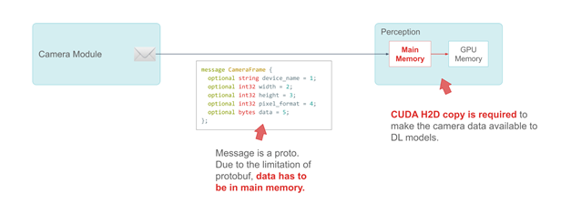
We use Google’s protobuf to define a message. Take the CameraFrame message as an example. Camera specs and attributes are primitive types in the message. The real payload—camera data—must be defined as a bytes field in the main system memory, due to the limitation of protobuf.
Figure 8. Example of a CameraFrame message
The message in the following code example is a proto. Due to the limitation of protobuf, data has to be in main memory.
CUDA H2D copy is required to make the camera data available to DL models.
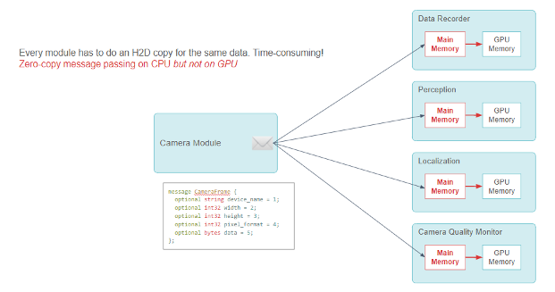
We use a publisher-subscriber model with zero-copy message passing among modules to share information. Many subscriber modules of this CameraFrame message use the camera data to make deep learning inferences.
In the original design, when such a module received the message, it would have had to call a CUDA HostToDevice memory copy to transfer the camera data to the GPU before the inference.
Figure 9. Block diagram showing a Publisher-Subscriber model that the camera module sends a CameraFrame message to multiple consumer modules. Each consumer module needs to do a CPU-to-GPU memory copy.
Every module has to do an H2D copy for the same data, which is time-consuming! The following code example shows the zero-copy message passing on the CPU but not on the GPU.
Every module must do the CUDA HostToDevice copy, which is redundant and resource-consuming. Although the zero-copy message passing framework works well on the CPU, it involves a lot of CPU-GPU data copy.
Figure 10. Zero-copy publisher-subscriber message passing with GPU support
We used the protobuf codegen plugin to enable the data fields in the GPU memory. The following code example shows the zero-copy message passing on the GPU. The GPUData field is in GPU memory.
We solved this issue by adding a new type of data, the GpuData field, into the protobuf code generator through protobuf’s plug-in API. GpuData supports the standard resize operation just like the CPU memory bytes field. However, its physical data storage is on-GPU.
When the subscriber modules receive the message, they can retrieve the GPU data pointer for direct use. Thus, we achieved full zero-copy throughout the entire pipeline.
Improving GPU memory allocation
When we call the resize function of the GpuData proto, it calls CUDA cudaMalloc. When the GpuData proto message is destroyed, it calls cudaFree.
These two API operations are not cheap because they must modify the GPU’s memory map. Each call could take ~0.1 ms.
Because this proto message is extensively used while the cameras are producing data non-stop, we should optimize the alloc/free cost of the GPU proto message.
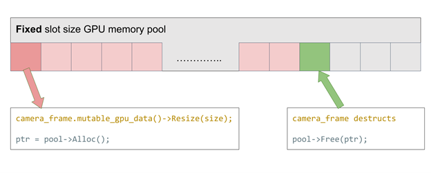
We implemented a fixed slot-size GPU memory to address this problem. The idea is simple: We maintain a stack of preallocated GPU memory slots that match our desired camera data frame buffer size. Every time alloc is called, we take one slot from the stack. Every time free is called, the slot is returned to the pool. The alloc/free time is near zero by re-using the GPU memory.
Figure 11. GPU memory pool supporting fixed allocation size only
What if we want to support cameras with different resolutions? Using this fixed-size memory pool, we must always allocate the largest possible size or initialize multiple memory pools with varying slot sizes. Either reduces efficiency.
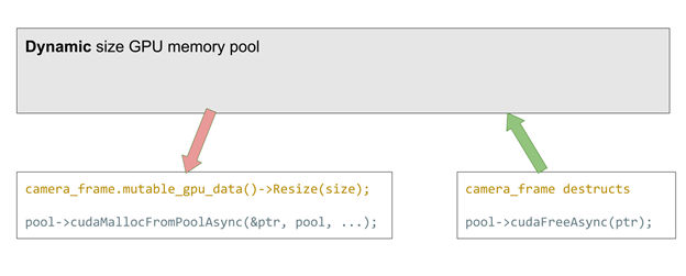
New features in CUDA 11.2 solved this issue. It officially supports cudaMemPool, which can be preallocated and later used for cudaMalloc and free. Compared with our previous implementation, it helps any allocation size. This greatly improves the flexibility at a tiny performance cost (~2us each allocation).
Figure 12. GPU memory pool supporting dynamic allocation size
camera_frame.mutable_gpu_data()->Resize(size);
pool->cudaMallocFromPoolAsync(&ptr, pool, ...);
camera_frame destructs
pool->cudaFreeAsync(ptr);
In both methods, the resize call falls back to conventional cudaMalloc and free when a memory pool overflows.
Cleaner data flow in YUV color space
We have achieved a highly efficient data flow with all the preceding optimizations of the hardware design and system software architecture. The next step is to optimize the data format itself.
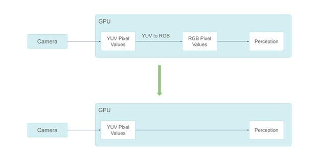
Our system used to process camera data in RGB color space. However, the ISP output of our cameras is in the YUV color space, and a conversion from YUV to RGB is performed on GPU, which takes ~0.3 ms. Also, some perception components do not need color information. Feeding RGB color pixels to them is wasteful.
Figure 13. Using the YUV format eliminates the colorspace conversion
For these reasons, we migrated from the RGB camera frames to the YUV frames. We chose to use the YUV420 pixel format because human vision is not as sensitive to chrominance information as to luminance information.
By adopting the YUV420 pixel format, we saved half of the GPU memory consumption. This also enabled us to send only the Y channel to the perception components, which do not require chrominance information, saving two-thirds of the GPU memory consumption compared to RGB.
Processing lidar data on-GPU
Besides camera data, we also process lidar data, which is more sparse, mostly on-GPU. While considering different types of Lidars, it is more difficult to process. We have taken several optimizations when processing lidar data:
Because lidar scan data contains a lot of physical information, we use the GPU-friendly Structure of Array instead of Array of Structures to describe the point cloud, making the GPU memory access pattern more coalesced instead of being scattered.
When some fields must be exchanged between CPU and GPU, we keep them in page-locked memory to accelerate the transfer.
The NVIDIA CUB library is extensively used in our processing pipeline, specifically the scan/select operations.
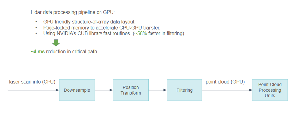
Figure 14. Block diagram showing pipeline from lidar sensor, to point cloud processing on GPU.
Lidar data processing pipeline on GPU produces the following results:
A GPU-friendly structure-of-array data layout.
Page-locked memory to accelerate the CPU-GPU transfer.
NVIDIA CUB library fast routines that are ~58% faster in filtering.
We have reduced the entire pipeline latency by ~4 ms in the critical path with all these optimizations.
Overall timeline
With all these optimizations, we can view our system tracing using our in-house timeline visualization tool.
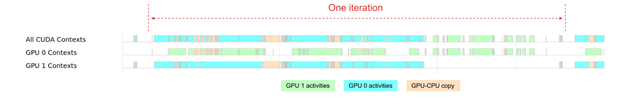
Figure 15. Overall timeline from sensor data to DL inference
The overall timeline shows the broad idea of how intensively we rely on our GPU today. Though the two GPUs are used for ~80% of the time, the workload of GPU0 and GPU1 are not ideally balanced. For GPU 0, it is heavily used throughout the perception module iteration. For GPU 1, it has more idle gaps in the middle of the iteration.
In the future, we will focus on further improving GPU efficiency.
Production-readiness
In the early days of development, the FPGA enabled us to easily experiment with our ideas in hardware-based sensor data processing. As our sensor-data processing unit becomes increasingly mature, we have been looking into the possibility of using a system-on-a-chip (SoC) to deliver a compact, reliable, and production-ready sensor data processor.
We found that the automotive-grade NVIDIA DRIVE Orin SoC perfectly meets our requirements. It is ASIL-rated, making it a great fit to run on production vehicles.
Migrating from FPGA to NVIDIA DRIVE Orin
In the early days of development, the FPGA enabled us to easily experiment with our ideas in hardware-based sensor data processing.
As our sensor-data processing unit becomes increasingly mature, we have been looking into the possibility of using a system-on-a-chip (SoC) to deliver a compact, reliable, and production-ready sensor data processor.
We found that the automotive-grade NVIDIA DRIVE Orin SoC perfectly meets our requirements. It is ASIL-rated, making it a great fit to run on production vehicles. Despite its compact size and low cost, it can connect to a wide spectrum of automotive-grade sensors and efficiently process large-scale sensor data.
We are going to use NVIDIA Orin to handle all the sensor signal processing, synchronization, packet collection, as well as camera frame encoding. We estimated that this design, combined with other architectural optimization, will save ~70% total BOM cost.
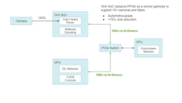
Figure 16. Using NVIDIA DRIVE Orin SoC as the new sensor gateway
Orin SoC replaces FPGA as a sensor gateway to support 10+ cameras and lidars, which are automotive-grade, for a ~70% cost reduction.
In collaboration with NVIDIA, we ensured that all communication among the Orin-CPU-GPU components goes through the PCIe bus with DMA support through NvStreams.
For compute-intensive DL work, the NVIDIA Orin SoC uses NvStream to transfer sensor data to the discrete GPU to process.
For non-GPU work, the NVIDIA Orin SoC uses NvStream to transfer data to the host CPU to process.
A level 2/3 compute platform application
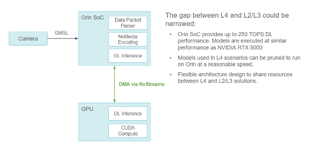
Figure 17. Block diagram showing a L2/L3 system camera pipeline achieved by removing the X86 CPU.
The gap between L4 and L2/L3 could be narrowed as Orin SoC provides up to 250 TOPS DL performance. Models are executed at a similar performance as NVIDIA RTX 5000, so models used in L4 scenarios can be pruned to run on Orin at a reasonable speed. The flexible architecture design can share resources between the L4 and L2/L3 solutions.
An excellent benefit of this design is that it has the potential to be used as an L2/L3 compute platform.
NVIDIA Orin provides 254 trillion operations per second of compute power that could potentially handle a similar workload as the RTX5000 discrete GPU being used on our current level 4 autonomous vehicle compute platform. However, it requires multiple optimizations to fully unleash the potential of the NVIDIA Orin SoC, such as:
Structural sparse network
DLA cores
Scaling across multiple NVIDIA Orin SoCs
Conclusion
The evolution of Pony’s sensor data processing pipeline has demonstrated our systematic approach toward high-efficiency data processing pipeline and enhanced system reliability, which helps achieve higher safety goals. The simple ideas behind this approach are:
Make the data flow simple and smooth. Data should be transferred directly to the location where it will get consumed, in the format that minimizes conversion overhead.
Use dedicated hardware for computation-intensive tasks and save the general-purpose computing resources for other tasks.
Resource sharing between level 4 and level 2 systems improves reliability and saves engineering costs.
This approach cannot be achieved by software or hardware alone, but by a joint effort of software and hardware co-design. We believe that this is crucial to satisfy the fast-growing computing needs with the production expectations.
Acknowledgments
This post includes years of evolution in Pony’s sensor data pipeline. The credit belongs to multiple teams and engineers who have continuously contributed to developing this highly efficient sensor data pipeline.
About a month back, I reported what I think is a security issue in the tensorflow/models repository. I disclosed this bug via huntr.dev as they had previous submissions to the repository. The security policy of the repository states that the security team gets back within 24 hours but it’s been a month and I haven’t heard back from them. The members at huntr.dev were kind enough to leave the following comment but I was wondering if there was a better way to do this. Thanks 😀
When it comes to safety, efficiency and sustainability, autonomous vehicles are delivering a clean sweep. Autonomous vehicle company and NVIDIA Inception member WeRide this month began a public road pilot of its Robo Street Sweepers. The vehicles, designed to perform round-the-clock cleaning services, are built on the high-performance, energy-efficient compute of NVIDIA. The fleet of Read article >
Choose from a range of workload-specific validated configurations for GPU-accelerated servers and workstations.
GPU-accelerated workloads are thriving across all industries, from the use of AI for better customer engagement and data analytics for business forecasting to advanced visualization for quicker product innovation.
One of the biggest challenges with GPU-accelerated infrastructure is choosing the right hardware systems. While the line of business cares about performance and the ability to use a large set of developer tools and frameworks, enterprise IT teams are additionally concerned with factors such as management and security.
The NVIDIA-Certified Systems program was created to answer the needs of both groups. Systems from leading system manufacturers equipped with NVIDIA GPUs and network adapters are put through a rigorous test process. A server or workstation is stamped as NVIDIA-Certified if it meets specific criteria for performance and scalability on a range of GPU-accelerated applications, as well as proper functionality for security and management capabilities.
Server configuration challenges
The certification tests for each candidate system are performed by the system manufacturer in their labs, and NVIDIA works with each partner to help them determine the best passing configuration. NVIDIA has studied hundreds of results across many server models, and this experience has allowed us to identify and solve configuration issues that can negatively impact performance.
High operating temperature
GPUs have a maximum supported temperature, but operating at a lower temperature can improve performance. A typical server has multiple fans to provide air cooling, with programmable temperature-speed fan curves. A default fan curve is based on a generic base system and does not account for the presence of GPUs and similar devices that can produce a lot of heat. The certification process can reveal performance issues due to temperature and can determine which custom fan curves give best results.
Non-optimal BIOS and firmware settings
BIOS settings and firmware versions can impact performance as well as functionality. The certification process validates the optimal BIOS settings for best performance and identifies the best values for other configurations, such as NIC PCI settings and boot grub settings.
Improper PCI slot configuration
Rapid transfer of data to the GPU is critical to getting the best performance. Because GPUs and NICs are installed on enterprise systems through the PCI bus, improper placement can result in suboptimal performance. The certification process exposes these issues and determines the optimal PCI slot configuration.
Certification goals
The certification is designed to exercise the performance and functionality of the candidate system by running a suite of more than 25 software tests that represent a wide range of real-world applications and operations.
The goal of these tests is to optimize a given system configuration for performance, manageability, security, and scalability.
Figure 1. NVIDIA-Certified Systems test suite
Performance
The test suite includes a diverse set of applications that stress the system in multiple ways. They cover the following issues:
Deep learning training and AI inference
End-to-end AI frameworks such as NVIDIA Riva and NVIDIA Clara
Data science applications such as Apache Spark and RAPIDS
Intelligent video analytics
HPC and CUDA functions
Rendering with Blender, Octane, and similar tools
Manageability
Certification tests are run on the NVIDIA Cloud Native core software stack using Kubernetes for orchestration. This validates that the certified servers can be fully managed by leading cloud-native frameworks, such as Red Hat OpenShift, VMware Tanzu, and NVIDIA Fleet Command.
Remote management capabilities using Redfish are also validated.
Security
The certification analyzes the platform-level security of hardware, devices, system firmware, low-level protection mechanisms, and the configuration of various platform components.
Trusted Platform Module (TPM) functionality is also verified, which enables the system to support features like secure boot, signed containers, and encrypted disk volumes.
Scalability
NVIDIA-Certified data center servers are tested to validate multi-GPU and multi-node performance using GPUDirect RDMA, as well as performance running multiple workloads using Multi-Instance GPU (MIG). There are also tests of key network services. These capabilities enable IT systems to scale accelerated infrastructure to meet workload demands.
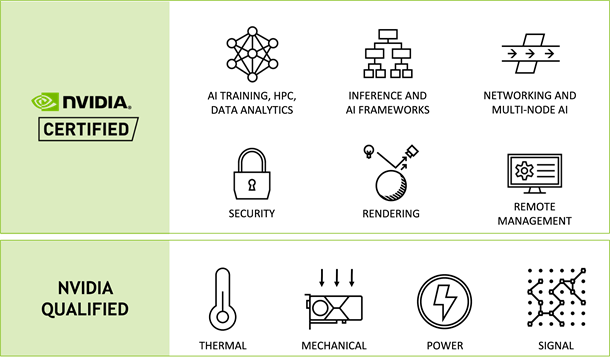
Qualification vs. certification
It’s important to understand the difference between qualification and NVIDIA certification. A qualified server has undergone thermal, mechanical, power, and signal integrity tests to ensure that a particular NVIDIA GPU is fully functional in that server design.
Servers in qualified configurations are supported for production use, and qualification is a prerequisite for certification. However, if you want a system that is both supported and optimally designed and configured, you should always choose a certified system.
Figure 2. NVIDIA-Certified vs. NVIDIA Qualified systems
NVIDIA-Certified system categories
NVIDIA-Certified Systems are available in a range of categories that are optimized for particular use cases. You can choose a system from the category that best matches your needs.
The design of systems in each category is determined by the system models and GPUs best suited for the target workloads. For instance, enterprise-class servers can be provisioned with NVIDIA A100 or NVIDIA A40 for data centers, whereas compact servers can use NVIDIA A2 for the edge.
The certification process is also tailored to each category. For example, workstations are not tested for multinode applications, and industrial edge systems must pass all tests while running in the environment for which the system was designed, such as elevated temperatures.
Image and Video Analytics, Multi-access Edge Computing (MEC)
Industrial Edge
Edge Inferencing in industrial or rugged environments
Robotics, Medical instruments, Field-deployed Telco Equipment
Workstation
Design, Content Creation, Data Science
Product & Building Design, M&E Content Creation
Mobile Workstation
Design, Content Creation, Data Science, Software Development
Data Feature Exploration, Software Design
Table 1. Certified system categories
Push the easy button for enterprise IT
With NVIDIA-Certified Systems, you can confidently choose and configure performance-optimized servers and workstations to power accelerated computing workloads, both in smaller configurations and at scale. NVIDIA-Certified Systems provide the easiest way for you to be successful with all your accelerated computing projects.
A wide variety of system types are available, including popular data center and edge server models, as well as desktop and mobile workstations from a vast ecosystem of NVIDIA partners. For more information, see the following resources:
Learn about the characteristics of inference workloads and systems features needed to run them, particularly at the edge.
Inference is an important part of the machine learning lifecycle and occurs after you have trained your model. It is when a business realizes value from their AI investment. Common applications of AI include image classification (“this is an image of a tumor”), recommendation (“here is a movie you will like”), transcription of speech audio into text, and decision (“turn the car to the left”).
Systems for deep learning training require a lot of computing capabilities, but after an AI model has been trained, fewer resources are needed to run it in production. The most important factors in determining the system requirements for inference workloads are the model being run and the deployment location. This post discusses these areas, with a particular focus on AI inference at the edge.
AI model inference requirements
For help with determining the optimal inference deployment configuration, a tool like NVIDIA Triton Model Analyzer makes recommendations based on the specific AI models that are running. An inference compiler like NVIDIA TensorRT can reduce the resource requirements for inference by optimizing the model to run with the highest throughput and lowest latency while preserving accuracy.
Even with these optimizations, GPUs are still critical to achieving the business service level objectives SLAs and requirements for inference workloads. Results from the MLPerf 2.0 Inference benchmark demonstrate that NVIDIA GPUs are more than 100x faster than CPU-only systems. GPUs can also provide the low latency required for workloads that need a real-time response.
Deployment locations of inference workloads
AI inference workloads can be found both in the data center as well as at the edge. Examples of inference workloads running in a data center include recommender systems and natural language processing.
There is great variety in the way these workloads can be run. For example, many different models can be served simultaneously from the same servers, and there can be hundreds, thousands, or even tens of thousands of concurrent inference requests in flight. In addition, data center servers often run other workloads besides AI inference.
There is no “one size fits all” solution when it comes to system design for data center inference.
Inference applications running at edge locations represent an important and growing class of workloads. Edge computing is driven by the requirement for low-latency, real-time results as well as the desire to reduce data transit for both cost and security reasons. Edge systems run in locations physically close to where data is collected or processed, in settings such as retail stores, factory floors, and cell phone base stations.
As compared with data center inference, system requirements for AI inference at the edge are easier to articulate, because these systems are usually designed to focus on a narrow range of inference workloads.
Edge inference typically involves either a camera or other sensor gathering data that must be acted upon. An example of this could be sensor-equipped video cameras in chemical plants being used to detect corrosion in pipes and alert staff before any damage is done.
Edge inference system requirements
Servers for AI training must be designed to process large amounts of historical data to learn the right values for model parameters. By contrast, servers for edge inference are required to process streaming data being gathered in real time at the edge location, which is smaller in volume.
As a result, system memory doesn’t need to be as large, and the number of CPU cores can be lower. The network adapter doesn’t need as high bandwidth and the local storage on the server can be smaller as it’s not caching any training data sets.
However, both the networking and storage should be configured to enable the lowest latency, as the ability to respond as quickly as possible is critical.
Resource
AI training in the data center
AI inferencing at the edge
CPU
Fastest CPUs with high core count
Lower-power CPUs
GPU
Fastest GPUs with most memory, more GPUs per system
Lower-power GPU, or larger GPU with MIG, one or two GPUs per system
Memory
Large memory size
Average memory size
Storage
High bandwidth NVMe flash drive, one per CPU
Average bandwidth, lowest-latency NVMe flash drive, one per system
Network
Highest bandwidth network adapter, Ethernet or InfiniBand, one per GPU pair
Average bandwidth network adapter, Ethernet, one per system
PCIe System
Devices balanced across PCIe topology; PCIe switch for multi-GPU, multi-NIC deployments
Devices balanced across PCIe topology; PCIe switch not required
Table 1. Resource recommendations for data center training and edge inferencing
Edge systems are by definition deployed outside traditional data centers, often in remote locations. The environment is often constrained in terms of space and power. These constraints can be met by using smaller systems in conjunction with low-powered GPUs, such as the NVIDIA A2.
If the inference workload is more demanding, and power budgets allow it, then a larger GPU, such as the NVIDIA A30 or NVIDIA A100, can be used. The Multi-Instance GPU (MIG) feature enables these GPUs to service multiple inference streams simultaneously so that the system overall can provide highly efficient performance.
Other factors for edge inference
Beyond system requirements, there are other factors to consider that are unique to the edge.
Host security
Security is a critical aspect of edge systems. Data centers by their nature can provide a level of physical control as well as centralized management that can prevent or mitigate attempts to steal information or take control of servers.
Edge systems must be designed with the assumption that their deployment locations are not physically secured, and that they cannot benefit from as many of the access control mechanisms found in data center IT management systems.
Trusted Platform Module (TPM) is one technology that can help greatly with host security. Configured appropriately, a TPM can ensure that the system can only boot with firmware and software that has been digitally signed and unaltered. Additional security checks such as signed containers ensure that applications haven’t been tampered with, and disk volumes can be encrypted with keys that are securely stored in the TPM.
Encryption
Another important consideration is the encryption of all network traffic to and from the edge system. Signed network adapters with encryption acceleration hardware, as found in NVIDIA ConnectX products, ensure that this protection doesn’t come at the expense of a reduction in data transfer rates.
Ruggedized systems
For certain use cases, such as on a factory floor for automation control or in an enclosure next to a telecommunications antenna tower, edge systems must perform well under potentially harsh conditions, such as elevated temperatures, large shock and vibration, and dust.
Ruggedized servers designed for these purposes are increasingly available with GPUs, thus allowing even these extreme use cases to benefit from greatly higher performance.
Choose an end-to-end platform for inference
NVIDIA has extended the NVIDIA-Certified Systems program to include categories for edge deployments that run outside a traditional data center. The design criteria for these systems include all of the following:
NVIDIA GPUs
CPU, memory, and network configurations that provide optimal performance
Security and remote management capabilities
The Qualified System Catalog has a list of NVIDIA-Certified systems from NVIDIA partners. The list can be filtered by category of system, including the following that are ideal for inference workloads:
Data Center servers are validated for performance and scale-out capabilities on a variety of data science workloads and are ideal for data center inference.
Enterprise Edge systems are designed to be deployed in controlled environments, such as the back office of a retail store. Systems in this category are tested in data center-like environments.
Industrial Edge systems are designed for industrial or rugged environments, such as a factory floor or cell phone tower base station. Systems that achieve this certification must pass all tests while running within the environment for which the system was designed, such as elevated temperature environments outside of the typical data center range.
In addition to certifying systems for the edge, NVIDIA has also developed enterprise software to run and manage inference workloads.
NVIDIA Triton Inference Server streamlines AI inference by enabling teams to deploy, run, and scale trained AI models from any framework on any GPU- or CPU-based infrastructure. It helps you deliver high-performance inference across cloud, on-premises, edge, and embedded devices.
NVIDIA AI Enterprise is an end-to-end, cloud-native suite of AI and data analytics software, optimized so every organization can be good at AI, certified to deploy in both data center and edge locations. It includes global enterprise support so that AI projects stay on track.
NVIDIA Fleet Command is a cloud service that centrally connects systems at edge locations to securely deploy, manage, and scale AI applications from one dashboard. It’s turnkey with layers of security protocols and can be fully functional in hours.
By choosing an end-to-end platform consisting of certified systems and infrastructure software, you can kick-start your AI production deployments and have inference applications deployed and running much more quickly than trying to assemble a solution from individual components.
Learn more about the NVIDIA AI Inference platform
There’s a lot more involved when it comes to deep learning inference. The NVIDIA AI Inference Platform Technical Overview has an in-depth discussion of this topic, including a view of the end-to-end deep learning workflow, the details of taking AI-enabled applications from prototype to production deployments, and software frameworks for building and running AI inference applications.
Sign up for Edge AI News to stay up to date with the latest trends, customer use cases, and technical walkthroughs.
Johnathan Stephens provides a walkthrough of how he started using Instant NeRF.
The new NVIDIA NGP Instant NeRF is a great introduction to getting started with neural radiance fields. In as little as an hour, you can compile the codebase, prepare your images, and train your first NeRF. Unlike other NeRF implementations, Instant NeRF only takes a few minutes to train a great-looking visual.
In my hands-on video (embedded), I walk you through the ins and outs of making your first NeRF. I cover a couple of key tips to help you compile the codebase and explain how to capture good input imagery. I walk through the GUI interface and explain how to optimize your scene parameters. Finally, I show you have to create an animation from your scene.
Video 1. Hands-on with NVIDIA Instant NeRFs
Compiling the codebase
The codebase is straightforward to compile for experienced programmers and data scientists. Beginners can easily follow the detailed instructions provided in bycloudai’s fork from the main GitHub repository. Here are a few additional tips that helped with the installation process:
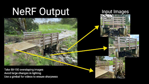
The pipeline accepts both photo and video input for Instant NeRF generation. The first step in the Instant NeRF generation pipeline uses COLMAP to determine camera positions. Due to this fact, you must follow basic principles of photogrammetry with respect to overlapping and sharp imagery. The video shows you example imagery from an ideal capture.
Figure 1. A few tips on input images to improve the quality of the NeRF output
Launching the GUI and training your first NeRF
When the images’ positions are prepared for your first Instant NeRF, launch the graphical user interface through Anaconda using the included Testbed.exe file compiled from the codebase. The NeRF automatically starts training your NeRF.
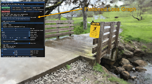
You will find a majority of visual quality gained in the first 30 seconds; however, your NeRF will continue to improve over several minutes. The loss graph in the GUI eventually flattens out and you can stop the training to improve your viewer’s framerate.
Figure 2. Snapshot of the GUI within the Instant NeRF software highlights the flattened loss graph
The GUI includes many visualization options, including controls over the camera and debug visualizations. I cover several different options in the GUI in the hands-on demo video.
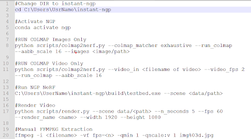
Tip: save your commonly used command-line prompts in Notepad for future reference.
Figure 3. Command-line prompts within the software
Creating an animation
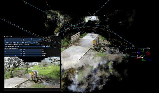
NVIDIA provides an easy-to-use camera path editor with the GUI. To add keyframes, navigate through the scene and choose Add from Cam. The GUI generates a camera trajectory with Bézier curves. To preview your animation, choose Read. When you are happy with the animation, save your camera path and render a full-quality video with the render script in your scripts folder.
Figure 4. Instant NeRF renders the static images into a 3D scene
Conclusion
One large benefit that I’ve found with Instant NeRFs is that I capture the entire background as part of the scene. Using photogrammetry, I lose the context of the object’s surroundings. This fact excites me as it unlocks a whole new world of potential for capturing and visualizing the world in new ways.
I found that experimenting with NVIDIA Instant NeRFs has been a great introduction to emerging technology. The speed at which I am able to produce results means that I can quickly learn about what works for image capturing. I hope that this walkthrough benefits you as you start your own journey to explore the power and fun of NeRFs.
Stay tuned
Now that you know how to capture a set of images and transform them into a 3D scene, we suggest you get practicing. NVIDIA will be hosting a competition for the chance to win the newest GPU to hit the market, an NVIDIA RTX 3090 Ti. Follow NVIDIA on Twitter and LinkedIn to stay in touch with the competition announcement in late May.

 Join NVIDIA and Google Cloud for a live webinar on May 25 to learn how to build a machine learning application to predict bike rental durations 5X faster.
 Here’s how Pony.ai, which develops autonomous driving systems for robotaxis and trucks, uses GPU technology to develop a highly efficient data processing pipeline.
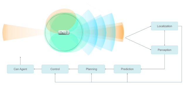

 Choose from a range of workload-specific validated configurations for GPU-accelerated servers and workstations.
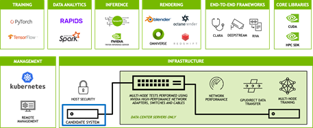
 Learn about the characteristics of inference workloads and systems features needed to run them, particularly at the edge.
 Johnathan Stephens provides a walkthrough of how he started using Instant NeRF.