
 PTP uses an algorithm and method for synchronizing clocks on various devices across packet-based networks to provide submicrosecond accuracy. NVIDIA Spectrum…
PTP uses an algorithm and method for synchronizing clocks on various devices across packet-based networks to provide submicrosecond accuracy. NVIDIA Spectrum supports PTP in both one-step and two-step modes and can serve either as a boundary or a transparent clock.
Here’s how the switch calculates and synchronizes time in one-step mode when acting as a transparent clock. Later in this post, I review overall PTP accuracy.
Calculating and synchronizing time in one-step mode
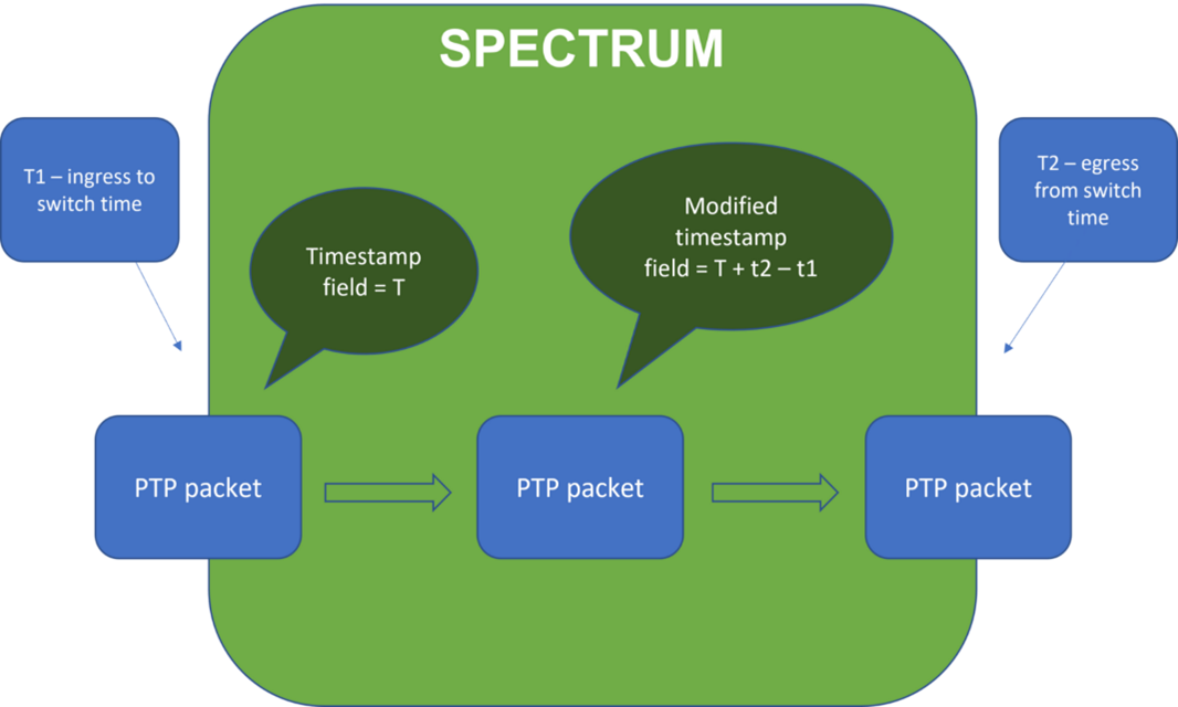
In one-step mode when acting as a transparent clock, the switch must calculate the residence time of a PTP packet in real time. It does this by comparing the time of the packet’s arrival (t1) with the time of the packet’s egress (t2). The switch then changes the correction field of the packet accordingly.
To perform this calculation, the switch uses several hardware features:
- A synchronized clock across the ASIC
- An accurate timestamp as the packet enters the switch
- A calculation of the time at which the packet will egress the switch
A synchronized clock across the ASIC
Because t1 at ingress and t2 at egress are on two different switch ports, time synchronization between different parts of the ASIC must be of high resolution to maintain an accurate comparison.
Having synchronized timestamps between different hardware units that sometimes work in different frequencies is challenging. The Spectrum family of ASICs can maintain synchronization errors smaller than 4 nanoseconds.
An accurate timestamp as the packet enters the switch
To achieve accurate one-step PTP, the switch must record the exact time at which it receives the packet.
As the switch receives bits from the line, it must assemble them, then parse and recognize the packet as PTP. This process takes time and must be considered so that there is no difference between the timestamp on the packet and the actual time at which the bits enter the switch.
To solve this challenge, the switch includes a designated hardware counter that calculates the number of bits between the line and the packet assembly. This counter can be translated to latency according to the protocol, then subtracted from the t1 timestamp to find the exact arrival time of the packet.
A calculation of the time at which the packet will egress the switch
Calculating the time at which the packet will egress the switch in advance is also a challenge. This is because the latency is typically affected by queuing and other parameters that are not accessible when the switch calculates the timestamp.
To solve this challenge, the switch schedules a future time for the packet to egress, then timestamps the packet according to this time. The PTP packet must then wait until the exact time to egress.
PTP scale
Other vendors use the software to match a PTP packet and its timestamp. The NVIDIA Spectrum-2 and later ASICs take a different approach. They handle PTP flows completely by hardware; nothing is required from software. There are many advantages to this implementation.
The Spectrum approach scales better for PTP flows and there is no burden on the switch’s limited compute resources. The scale is only limited by the CPU host capabilities when acting as a boundary clock. For a transparent clock, where no software is involved, there is technically no limit on the scale.
Software processing is serial and slower than hardware. Therefore, a PTP packet resides on the switch much longer if it requires software intervention. This process increases the delay between the primary and the follower entities in the network and can indirectly damage the synchronization process that assumes constant traversing time from point to point in the network.
PTP accuracy
The overall PTP accuracy of the NVIDIA Spectrum switch is around 10 nanoseconds. This accuracy is maintained for all speeds and FEC configuration.
The following graph demonstrates PTP accuracy on the Spectrum-3 switch.
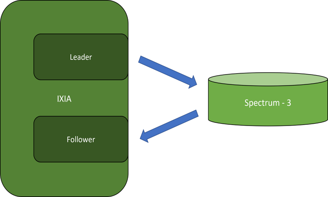

These results are taken from a one-hour test at a speed of 50 Gbps in which IXIA serves as a leader clock connected to an NVIDIA Spectrum-3 switch. The switch acts as a boundary clock. Another IXIA port serves as a follower and measures the time offset compared to the primary for each packet.
For more information, see the following resources:
- NVIDIA Cumulus Linux User Guide
- NVIDIA Cumulus Linux datasheet
- NVIDIA Cumulus Linux page
- NVIDIA Announces Spectrum High-Performance Data Center Networking Infrastructure Platform
- Precision Timing Protocol standard (2008, updated 2019)
- Time Appliances Project
- Time Synchronization in Distributed Data Centers