
 Accurate, fast object detection is an important task in robotic navigation and collision avoidance. Autonomous agents need a clear map of their surroundings to…
Accurate, fast object detection is an important task in robotic navigation and collision avoidance. Autonomous agents need a clear map of their surroundings to navigate to their destination while avoiding collisions. For example, in warehouses that use autonomous mobile robots (AMRs) to transport objects, avoiding hazardous machines that could potentially damage robots has become a challenging problem.
This post presents a ROS 2 node for detecting objects in point clouds using a pretrained model from NVIDIA TAO Toolkit based on PointPillars. The node takes point clouds as input from real or simulated lidar scans, performs TensorRT-optimized inference to detect objects in this input data, and outputs the resulting 3D bounding boxes as a Detection3DArray message for each point cloud.
While multiple ROS nodes exist for object detection from images, the advantages of performing object detection from lidar input include the following:
- Lidar can calculate accurate distances to many detected objects simultaneously. With object distance and direction information provided directly from lidar, it’s possible to get an accurate 3D map of the environment. To obtain the same information in camera/image-based systems, a separate distance estimation process is required which demands more compute power.
- Lidar is not sensitive to changing lighting conditions (including shadows and bright light), unlike cameras.
An autonomous system can be made more robust by using a combination of lidar and cameras. This is because cameras can perform tasks that lidar cannot, such as detecting text on a sign.
TAO-PointPillars is based on work presented in the paper, PointPillars: Fast Encoders for Object Detection from Point Clouds, which describes an encoder to learn features from point clouds organized in vertical columns (or pillars). TAO-PointPillars uses both the encoded features as well as the downstream detection network described in the paper.
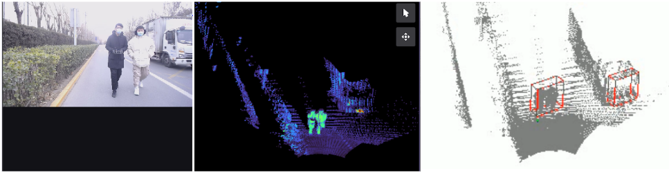
For our work, a PointPillar model was trained on a point cloud dataset collected by a solid state lidar from Zvision. The PointPillar model detects objects of three classes: Vehicle, Pedestrian, and Cyclist. You can train your own detection model following the TAO Toolkit 3D Object Detection steps, and use it with this node.
For details on running the node, visit NVIDIA-AI-IOT/ros2_tao_pointpillars on GitHub. You can also check out NVIDIA Isaac ROS for more hardware-accelerated ROS 2 packages provided by NVIDIA for various perception tasks.
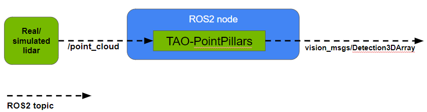
ROS 2 TAO-PointPillars node
This section provides more details about using the ROS 2 TAO-PointPillars node with your robotic application, including the input/output formats and how to visualize results.
Node Input: The node takes point clouds as input in the PointCloud2 message format. Among other information, point clouds must contain four features for each point (x, y, z, r) where (x, y, z, r) represent the X coordinate, Y coordinate, Z coordinate and reflectance (intensity), respectively.
Reflectance represents the fraction of a laser beam reflected back at some point in 3D space. Note that the range for reflectance values should be the same in the training data and inference data. Parameters including intensity range, class names, NMS IOU threshold can be set from the launch file of the node.
You can find ROS 2 bags for testing the node by visiting ZVISION-lidar/zvision_ugv_data on GitHub.
Node Output: The node outputs 3D bounding box information, object class ID, and score for each object detected in a point cloud in the Detection3DArray message format. Each 3D bounding box is represented by (x, y, z, dx, dy, dz, yaw) where (x, y, z, dx, dy, dz, yaw) are, respectively, the X coordinate of object center, Y coordinate of object center, Z coordinate of object center, length (in X direction), width (in Y direction), height (in Z direction) and orientation in 3D Euclidean space.
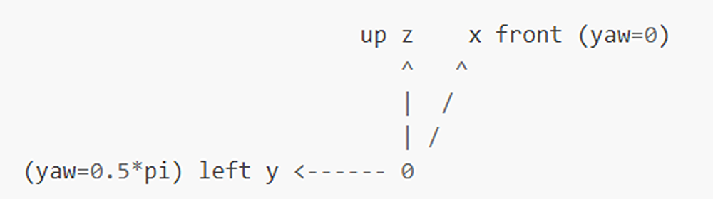
The coordinate system used by the model during training and that used by the input data during inference must be the same for meaningful results. Figure 3 shows the coordinate system used by the TAO-PointPillars model.
Since Detection3DArray messages cannot currently be visualized on RViz, you can find a simple tool to visualize results by visiting NVIDIA-AI-IOT/viz_3Dbbox_ros2_pointpillars on GitHub.
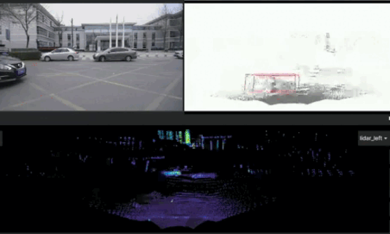
For the example shown in Figure 4 below, the frequency of input point clouds is ~10 FPS and of output Detection3DArray messages is ~10 FPS on Jetson AGX Orin.
Summary
Accurate object detection in real time is necessary for an autonomous agent to navigate its environment safely. This post showcases a ROS 2 node that can detect objects in point clouds using a pretrained TAO-PointPillars model. (Note that the TensorRT engine for the model currently only supports a batch size of one.) This model performs inference directly on lidar input, which maintains advantages over using image-based methods. For performing inference on lidar data, a model trained on data from the same lidar must be used. There will be a significant drop in accuracy otherwise, unless a method like statistical normalization is implemented.